LIN COMMUNICATION SYSTEM, Diagnostic DTC:B2321
| DTC Code | DTC Name |
|---|---|
| B2321 | Driver Side Door ECU Communication Stop |
DESCRIPTION
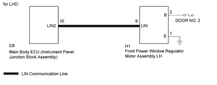
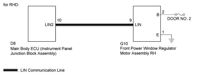
This DTC is output when LIN communication between the front power window regulator motor assembly LH*1/RH*2and main body ECU (instrument panel junction block assembly) stops for more than 10 seconds.
Tech Tips
*1: for LHD
*2: for RHD
| DTC No. | DTC Detection Condition | Trouble Area |
|---|---|---|
| B2321 | No communication between front power window regulator motor assembly LH*1/RH*2and main body ECU (instrument panel junction block assembly) for more than 10 seconds |
|
WIRING DIAGRAM
INSPECTION PROCEDURE
Note
When using the intelligent tester with the ignition switch off to troubleshoot:
Connect the intelligent tester to the vehicle, and turn the courtesy switch on and off at 1.5-second intervals until communication between the tester and vehicle begins.
PROCEDURE
-
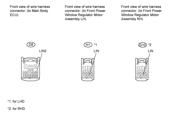
CHECK HARNESS AND CONNECTOR (MAIN BODY ECU - FRONT POWER WINDOW REGULATOR MOTOR LH*1/RH*2)
Tech Tips
*1: for LHD
*2: for RHD
-
Disconnect the D8 connector.
-
Disconnect the H1*1or G10*2connector.
-
Measure the resistance according to the value(s) in the table below.
Standard resistance Tester Connection Condition Specified Condition D8-10 (LIN2) - H1*1-9 (LIN)
Always Below 1 Ω D8-10 (LIN2) - G10*2-9 (LIN)
Always Below 1 Ω D8-10 (LIN2) - Body ground Always 10 kΩ or higher -
Measure the voltage according to the value(s) in the table below.
Standard voltage Tester Connection Condition Specified Condition D8-10 (LIN2) - Body ground Always Below 1 V
NG 
REPAIR OR REPLACE HARNESS OR CONNECTOR
OK 
-
-
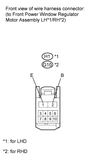
CHECK FRONT POWER WINDOW REGULATOR MOTOR ASSEMBLY LH*1/RH*2
Tech Tips
*1: for LHD
*2: for RHD
-
Disconnect the H1*1or G10*2connector.
-
Measure the resistance according to the value(s) in the table below.
Standard resistance Tester Connection Condition Specified Condition H1*1-2 (B) - Body ground
G10*2-2 (B) - Body ground
Always Below 1 Ω -
Measure the voltage according to the value(s) in the table below.
Standard voltage Tester Connection Condition Specified Condition H1*1-2 (B) - Body ground
G10*2-2 (B) - Body ground
Always 11 to 14 V
NG
REPAIR OR REPLACE HARNESS OR CONNECTOR
OK
-
-
REPLACE FRONT POWER WINDOW REGULATOR MOTOR ASSEMBLY LH*1/RH*2
Tech Tips
*1: for LHD
*2: for RHD
-
Replace the front power window regulator motor assembly LH*1or RH*2with a normally-functioning or a new one Click here.
-
Clear the DTC.
NEXT
-
-
CHECK FOR DTC
-
Recheck for DTC.
Result Result Proceed to B2321 is not output A B2321 is output B
B
REPLACE MAIN BODY ECU (INSTRUMENT PANEL JUNCTION BLOCK)
A 
END
-