LIN COMMUNICATION SYSTEM TERMINALS OF ECU
-
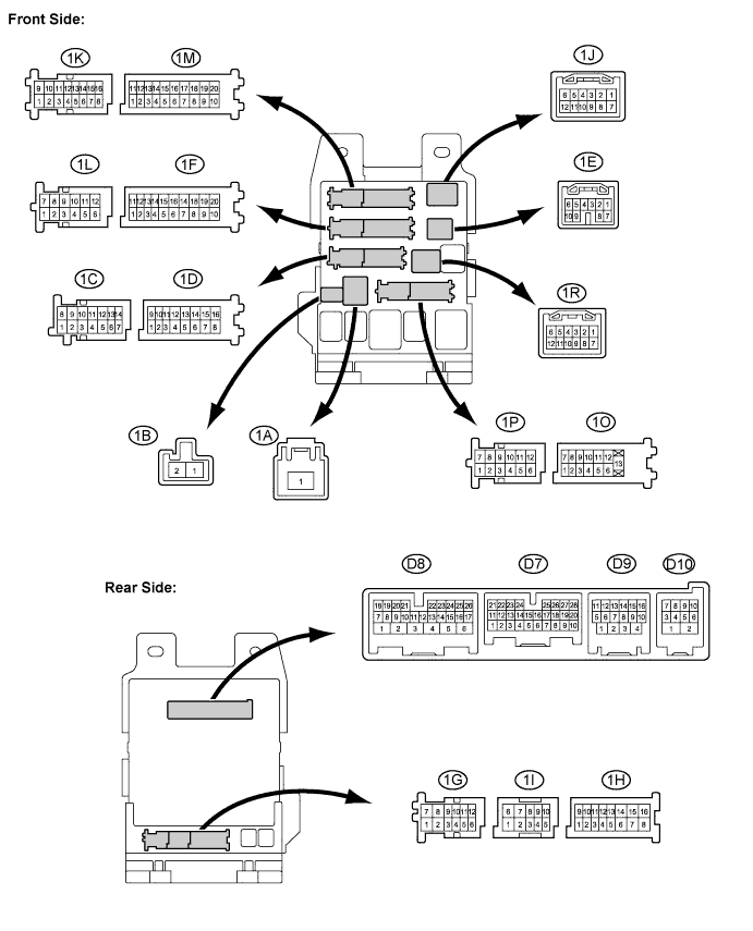
CHECK MAIN BODY ECU (INSTRUMENT PANEL JUNCTION BLOCK ASSEMBLY)
-
Disconnect the 1D, 1F, D6, and D7 instrument panel junction block assembly connectors.
-
Measure the voltage and resistance between the wire harness side connectors and body ground.
Terminal No. (Symbols) Wiring Color Terminal Description Condition Specified Condition 1D-10 (BECU)*1- Body ground
W - Body ground Battery power supply Always 11 to 14 V D7-6 (AM1)*2- Body ground
GR - Body ground Battery power supply Always 11 to 14 V D6-1 (AM2)*2- Body ground
G - Body ground Battery power supply Always 11 to 14 V 1F-10 (GND1) - Body ground W-B - Body ground Ground Always Below 1 Ω Tech Tips
-
If the result is not as specified, there may be a malfunction on the wire harness side.
-
*1: w/o Smart Entry and Start System
-
*2: w/ Smart Entry and Start System
-
-
Reconnect the 1D,1F, D6, and D7 instrument panel junction block assembly connectors.
-
Measure the pulse according to the value(s) in the table below.
Terminal No. (Symbols) Wiring Color Terminal Description Condition Specified Condition 1E-7 (LIN1)*2- 1F-10 (GND1)
R - W-B LIN Communication line Ignition switch on (IG) Pulse generation D8-10 (LIN2) - 1F-10 (GND1) P - W-B LIN Communication line Ignition switch on (IG) Pulse generation Tech Tips
-
If the result is not as specified, the main body ECU (Instrument panel junction block assembly) may be malfunctioning.
-
*2: w/ Smart Entry and Start System
-
-
-
CHECK POWER WINDOW REGULATOR MOTOR ASSEMBLY (for Driver Side)
-
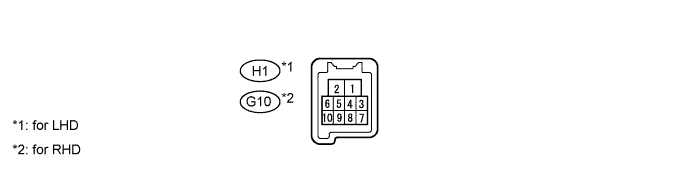
Disconnect the H1*1or G10*2motor connector.
-
Measure the voltage and resistance according to the value(s) in the table below.
for LHD: Terminal No. (Symbols) Wiring Color Terminal Description Condition Specified Condition H1-2 (B) - H1-1 (E) SB - W-B Battery power supply Always 11 to 14 V H1-1 (E) - Body ground W-B - Body ground Ground Always Below 1 Ω for RHD: Terminal No. (Symbols) Wiring Color Terminal Description Condition Specified Condition G10-2 (B) - G10-1 (E) SB - W-B Battery power supply Always 11 to 14 V G10-1 (E) - Body ground W-B - Body ground Ground Always Below 1 Ω Tech Tips
If the result is not as specified, there may be a malfunction on the wire harness side.
-
Reconnect the H1*1or G10*2motor connector.
-
Measure the pulse according to the value(s) in the table below.
for LHD: Terminal No. (Symbols) Wiring Color Terminal Description Condition Specified Condition H1-9 (LIN) - H1-1 (E) P - W-B LIN Communication line Ignition switch on (IG) Pulse generation for RHD: Terminal No. (Symbols) Wiring Color Terminal Description Condition Specified Condition G10-9 (LIN) - G10-1 (E) P - W-B LIN Communication line Ignition switch on (IG) Pulse generation Tech Tips
If the result is not as specified, the motor may be malfunctioning.
-
-
CHECK SLIDING ROOF ECU (SLIDING ROOF DRIVE GEAR SUB-ASSEMBLY) [w/ Sliding Roof]

-
Disconnect the Q12 ECU connector.
-
Measure the voltage and resistance according to the value(s) in the table below.
Terminal No. (Symbols) Wiring Color Terminal Description Condition Specified Condition Q12-1 (B) - Q12-2 (E) B - W-B Battery power supply Always 11 to 14 V Q12-2 (E) - Body ground W-B - Body ground Ground Always Below 1 Ω Tech Tips
If the result is not as specified, there may be a malfunction on the wire harness side.
-
Reconnect the Q12 ECU connector.
-
Measure the pulse according to the value(s) in the table below.
Terminal No. (Symbols) Wiring Color Terminal Description Condition Specified Condition Q12-4 (MPX1) - Q12-2 (E) P - W-B LIN Communication line Ignition switch on (IG) Pulse generation Tech Tips
If the result is not as specified, the ECU may be malfunctioning.
-
-
CHECK CERTIFICATION ECU (SMART KEY ECU ASSEMBLY) [w/ Smart Entry and Start System]
-
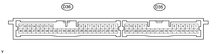
Disconnect the D36 ECU connector.
-
Measure the voltage and resistance according to the value(s) in the table below.
Terminal No. (Symbols) Wiring Color Terminal Description Condition Specified Condition D36-1 (+B) - D36-17 (E) B - B Battery power supply Always 10 to 14 V D36-17 (E) - Body ground B - Body ground Ground Always Below 1 Ω Tech Tips
If the result is not as specified, there may be a malfunction on the wire harness side.
-
Reconnect the D36 ECU connector.
-
Measure the pulse according to the value(s) in the table below.
Terminal No. (Symbols) Wiring Color Terminal Description Condition Specified Condition D36-10 (LIN) - D36-17 (E) L - B LIN Communication line Ignition switch on (IG) Pulse generation D36-18 (IG) - D36-17 (E) G - B Power supply Ignition switch on (IG) 10 to 14 V D36-18 (IG) - D36-17 (E) G - B Power supply Ignition switch off Below 1 Ω Tech Tips
If the result is not as specified, the ECU may be malfunctioning.
-
-
CHECK ID CODE BOX (IMMOBILISER CODE ECU) [w/ Smart Entry and Start System]

-
Disconnect the D28 ECU connector.
-
Measure the voltage and resistance according to the value(s) in the table below.
Terminal No. (Symbols) Wiring Color Terminal Description Condition Specified Condition D28-1 (+B) - D28-8 (GND) W - V Battery power supply Always 11 to 14 V D28-8 (GND) - Body ground V - Body ground Ground Always Below 1 Ω Tech Tips
If the result is not as specified, there may be a malfunction on the wire harness side.
-
Reconnect the D28 ECU connector.
-
Measure the pulse according to the value(s) in the table below.
Terminal No. (Symbols) Wiring Color Terminal Description Condition Specified Condition D28-3 (LIN1) - D28-8 (GND) LG - V LIN Communication line Ignition switch on (IG) Pulse generation Tech Tips
If the result is not as specified, the ECU may be malfunctioning.
-
-
CHECK STEERING LOCK ECU (STEERING LOCK ACTUATOR ASSEMBLY) [w/ Smart Entry and Start System]

-
Disconnect the D10 ECU connector.
-
Measure the voltage and resistance according to the value(s) in the table below.
Terminal No. (Symbols) Wiring Color Terminal Description Condition Specified Condition D10-1 (GND) - Body ground W-B - Body ground Ground Always Below 1 Ω D10-6 (IG2) - D10-1 (GND) V - W-B Power supply Ignition switch on (IG) 10 to 14 V D10-6 (IG2) - D10-1 (GND) V - W-B Power supply Ignition switch off Below 1 Ω D10-7 (B) - D10-1 (GND) G - W-B Battery power supply Always 10 to 14 V Tech Tips
If the result is not as specified, there may be a malfunction on the wire harness side.
-
Reconnect the D10 ECU connector.
-
Measure the pulse according to the value(s) in the table below.
Terminal No. (Symbols) Wiring Color Terminal Description Condition Specified Condition D10-5 (LIN) - D10-1 (GND) GR - W-B LIN Communication line Ignition switch on (IG) Pulse generation Tech Tips
If the result is not as specified, the ECU may be malfunctioning.
-