FRONT DOOR BELT MOULDING REMOVAL
-
DISCONNECT NEGATIVE BATTERY TERMINAL
CAUTION:
Wait for 90 seconds after disconnecting the terminal to prevent airbag deployment Click here.
Note
When disconnecting the cable, some systems need to be initialized after the cable is reconnected Click here.
-
REMOVE FRONT DOOR LOWER FRAME BRACKET GARNISH
-
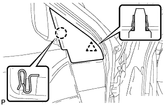
Disengage the claw and clip, and remove the front door lower frame bracket garnish.
-
-
REMOVE FRONT DOOR INSIDE HANDLE BEZEL PLUG
-
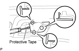
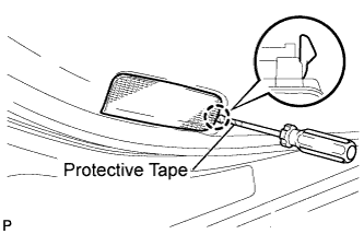
Using a screwdriver with the tip wrapped with protective tape, disengage the 3 claws, and remove the front door inside handle bezel plug.
-
-
REMOVE FRONT ARMREST UPPER BASE PANEL
-
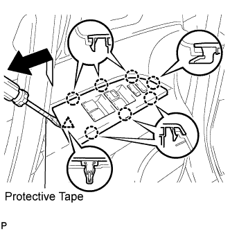
Using a screwdriver with the tip wrapped with protective tape, disengage the 7 claws and clip, and remove the front armrest upper base panel.
-
Disconnect the connector.
-
-
REMOVE ASSIST GRIP COVER
-
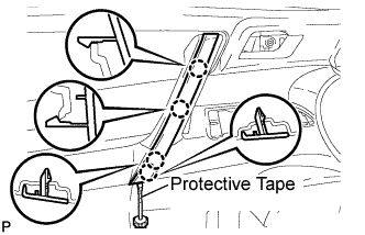
Using a screwdriver with the tip wrapped with protective tape, disengage the 4 claws and remove the assist grip cover.
-
-
REMOVE COURTESY LIGHT ASSEMBLY
-
Using a screwdriver with the tip wrapped with protective tape, disengage the claw and remove the courtesy light assembly.
-
Disconnect the connector.
-
-
REMOVE FRONT DOOR TRIM BOARD SUB-ASSEMBLY
-
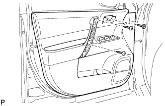
Remove the 3 screws.
-
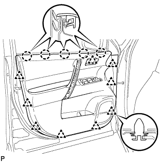
Using a clip remover, disengage the 9 clips.
-
Disengage the 5 claws and separate the front door trim board sub-assembly from the front door inner glass weatherstrip.
-
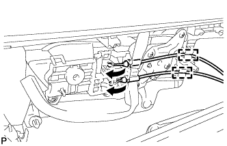
Disengage the 2 clamps.
-
Disconnect the front door lock remote control cable and front door inside locking cable.
-
Disconnect the connector.
-
-
REMOVE FRONT DOOR INNER GLASS WEATHERSTRIP
-
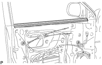
Remove the front door inner glass weatherstrip from the front door panel.
-
-
REMOVE FRONT NO. 1 SPEAKER ASSEMBLY
-
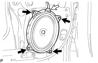
Disconnect the connector.
-
Remove the 4 bolts and front No. 1 speaker assembly.
Note
Do not touch the cone part of the speaker.
-
-
REMOVE OUTER REAR VIEW MIRROR ASSEMBLY WITH COVER
-
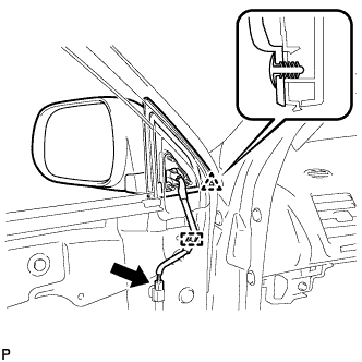
Disconnect the connector and clamp.
-
Disengage the clip.
-
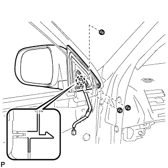
Remove the 3 nuts.
-
Disengage the claw and remove the outer rear view mirror assembly with cover.
-
-
REMOVE FRONT DOOR SERVICE HOLE COVER
-
Disconnect the each connector and 2 clamps, and remove the front door service hole cover.
Tech Tips
Remove the remaining butyl tape on the door side.
-
-
REMOVE FRONT DOOR GLASS SUB-ASSEMBLY
-
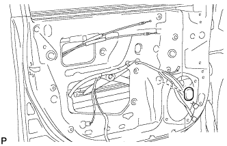
Remove the hole plug.
-
Connect the negative battery terminal.
-
Connect the power window regulator motor connector.
-
Connect the power window regulator master switch assembly and move the front door glass sub-assembly so that the door glass bolts can be seen.
-
Disconnect the negative battery terminal and power window regulator master switch assembly.
-
Disconnect the power window regulator motor connector.
-
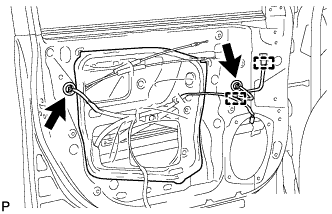
Remove the 2 bolts.
Note
After the bolts are removed, do not allow the door to fall.
-
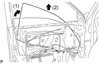
Remove the front door glass sub-assembly as shown in the illustration.
Note
Do not damage the door glass.
-
-
REMOVE FRONT DOOR WINDOW REGULATOR SUB-ASSEMBLY
-
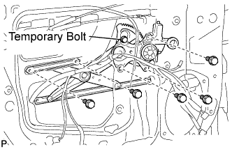
Loosen the temporary bolt.
Note
Do not remove the temporary bolt. If the temporary bolt is removed, the front door window regulator may fall and cause damage.
-
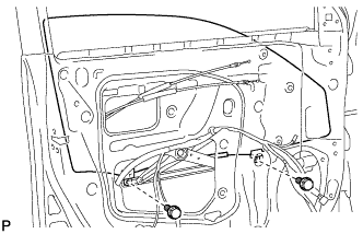
Remove the 5 bolts.
-
Remove the front door window regulator sub-assembly and the front power window regulator motor assembly as a unit.
-
Remove the temporary bolt from the front door window regulator sub-assembly.
-
-
REMOVE FRONT DOOR BELT MOULDING ASSEMBLY
-
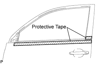
Put protective tape around the front door belt moulding assembly.
-
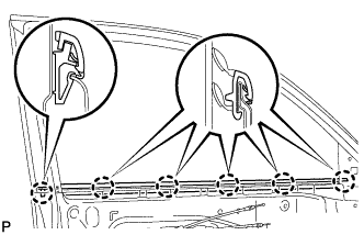
Disengage the 6 claws and remove the front door belt moulding assembly.
Note
Be careful when removing the moulding as there are claws attached to the front and rear ends of the moulding.
-