ROOF HEADLINING REMOVAL
-
REMOVE REAR CENTER SEAT ASSEMBLY
-
REMOVE REAR SEAT HEADREST ASSEMBLY (for LH Side)
-
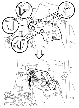
REMOVE REAR SEAT TRACK BRACKET COVER LH
-
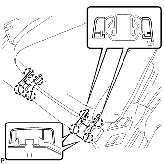
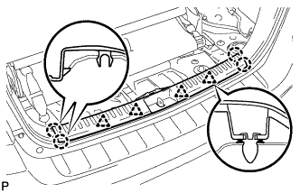
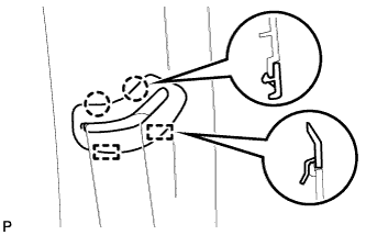
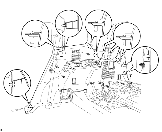
Disengage the 8 claws and remove the 2 rear seat track bracket covers.
-
-
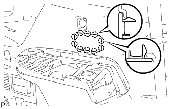
REMOVE REAR OUTER TRACK BRACKET COVER LH
-
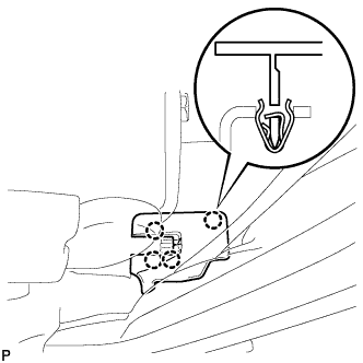
Disengage the 4 claws and remove the rear outer track bracket cover.
-
-
REMOVE REAR INNER TRACK BRACKET COVER LH
-
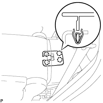
Disengage the 4 claws and remove the rear inner track bracket cover.
-
-
REMOVE REAR SEAT LEG SIDE COVER LH
-
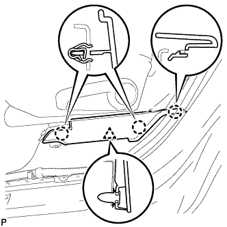
Disengage the 3 claws.
-
Disengage the clip and remove the rear seat leg side cover.
-
-
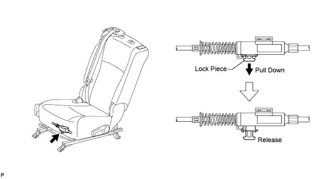
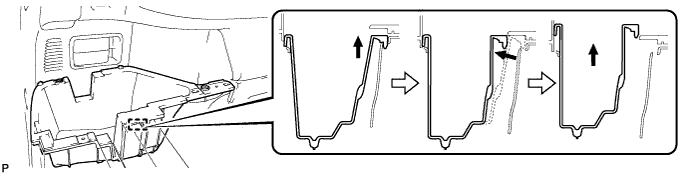
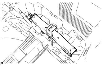
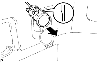
DISCONNECT REAR NO. 1 SEAT LOCK CABLE ASSEMBLY LH (w/ Remote Folding Function)
-
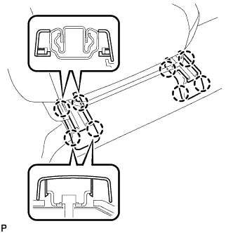
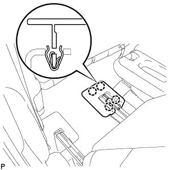
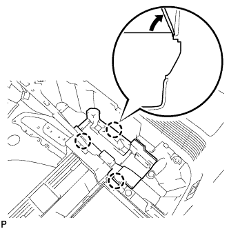
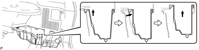
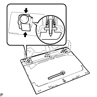
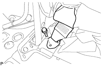
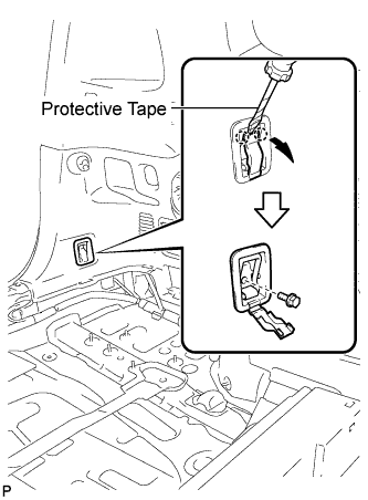
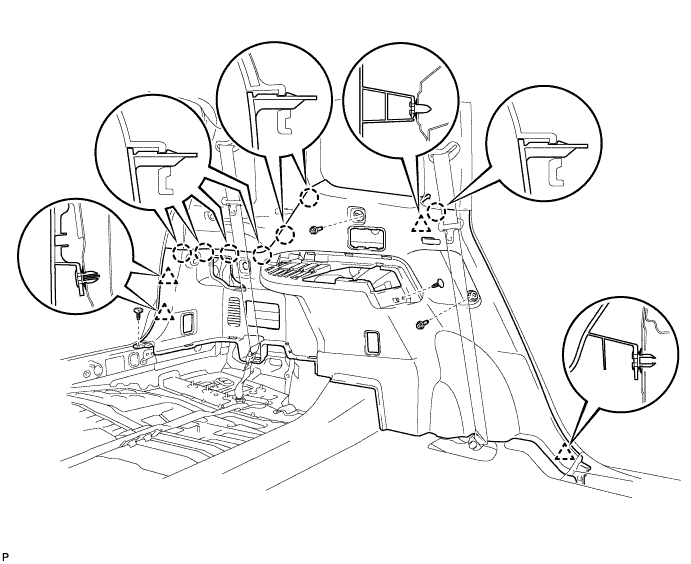
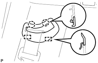
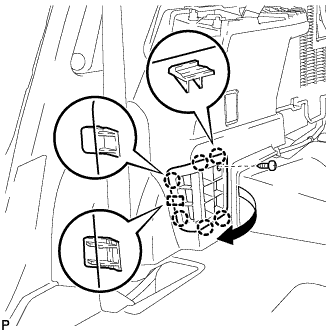
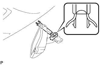
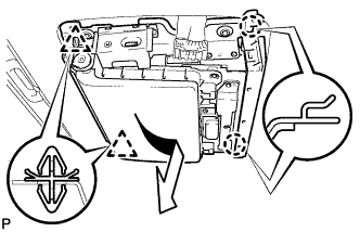
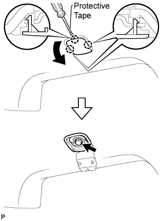
Pull down the adjuster's lock piece to release the lock as shown in the illustration.
-
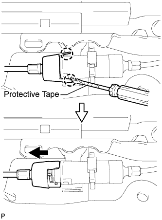
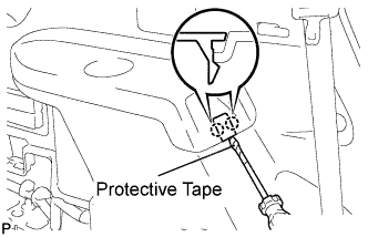
Using a screwdriver wrapped with protective tape, disengage the 2 claws as shown in the illustration.
-
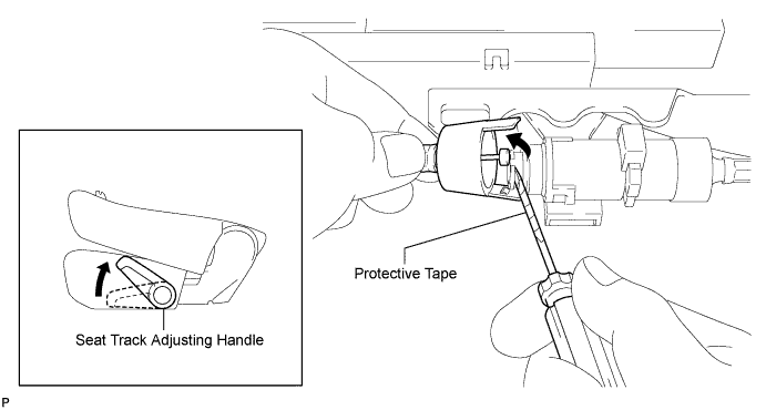
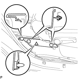
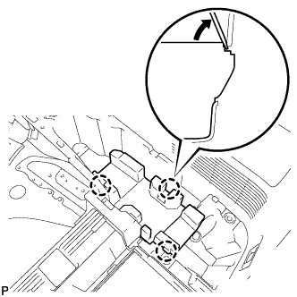
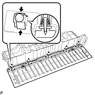
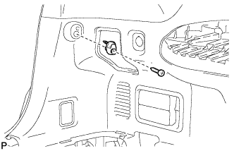
Lift up the seat track adjusting handle to the uppermost position and hold the handle in this position as shown in the illustration.
-
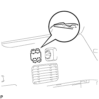
Using a screwdriver wrapped with protective tape, disconnect the rear No. 1 seat lock cable assembly as shown in the illustration.
-
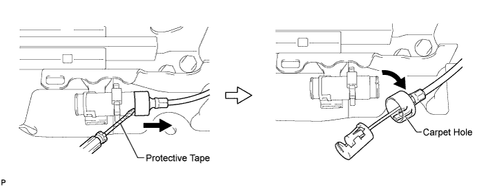
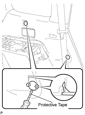
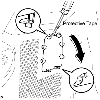
Using a screwdriver wrapped with protective tape, disconnect the rear seat reclining control cable as shown in the illustration.
-
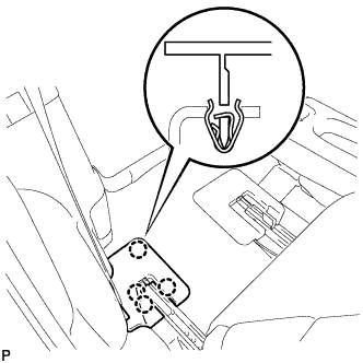
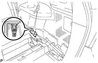
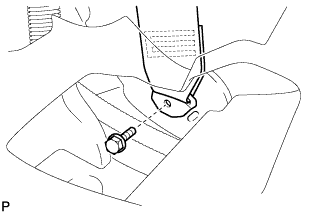
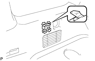
Secure the rear seat reclining control cable with the carpet hole as shown in the illustration.
-
-
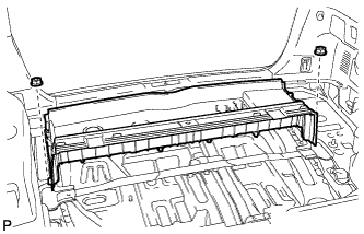
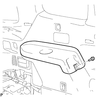
REMOVE REAR NO. 1 SEAT ASSEMBLY LH
-
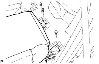
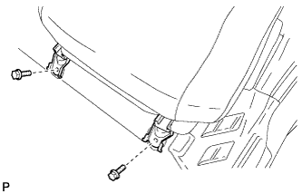
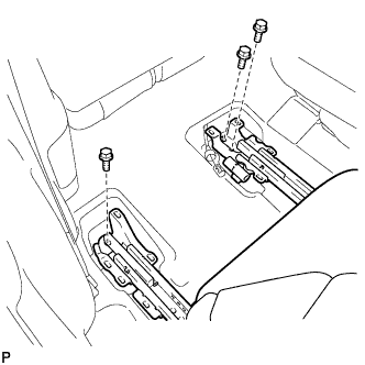
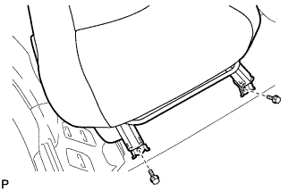
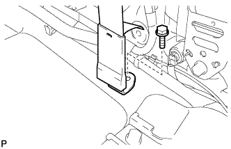
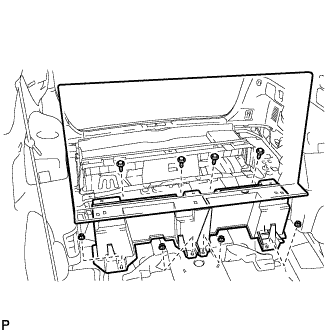
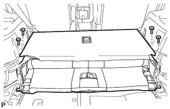
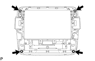
Remove the 3 bolts on the rear side of the seat.
-
Remove the 2 bolts on the front side of the seat and the rear No. 1 seat assembly.
Note
Be careful not to damage the vehicle body.
-
-
REMOVE REAR SEAT HEADREST ASSEMBLY (for RH Side)
-
REMOVE REAR SEAT TRACK BRACKET COVER RH
-
Disengage the 8 claws and remove the 2 rear seat track bracket covers.
-
-
REMOVE REAR OUTER TRACK BRACKET COVER RH
-
Disengage the 4 claws and remove the rear outer track bracket cover.
-
-
REMOVE REAR INNER TRACK BRACKET COVER RH
-
Disengage the 4 claws and remove the rear inner track bracket cover.
-
-
REMOVE REAR SEAT LEG SIDE COVER RH
-
Disengage the 3 claws.
-
Disengage the clip and remove the rear seat leg side cover.
-
-
DISCONNECT REAR NO. 1 SEAT LOCK CABLE ASSEMBLY RH (w/ Remote Folding Function)
Tech Tips
Use the same procedure for the RH side and the LH side.
-
REMOVE REAR NO. 1 SEAT ASSEMBLY RH
-
Remove the 3 bolts on the rear side of the seat.
-
Remove the 2 bolts on the front side of the seat and the rear No. 1 seat assembly.
Note
Be careful not to damage the vehicle body.
-
-
REMOVE FRONT DOOR SCUFF PLATE LH
-

Disengage the 8 claws and guide, and remove the front door scuff plate LH.
-
-
REMOVE COWL SIDE TRIM SUB-ASSEMBLY LH
-

Remove the clip.
-
Disengage the clip and claw, and remove the cowl side trim sub-assembly LH.
-
-
REMOVE FRONT DOOR OPENING TRIM WEATHERSTRIP LH
-
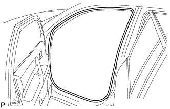
Remove the front door opening trim weatherstrip LH.
-
-
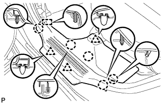
REMOVE FRONT PILLAR GARNISH LH
-
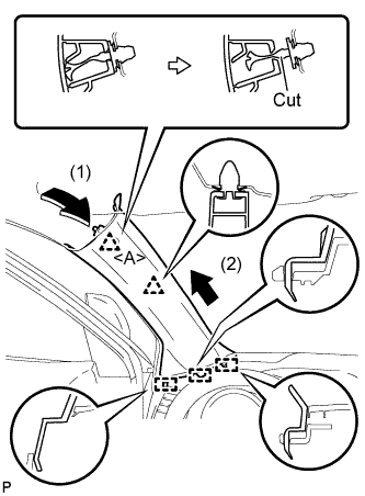
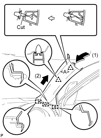
Pull the upper part of the garnish toward the inside of the cabin and disengage the 2 clips.
-
Cut off the clip <A>.
-
Disengage the 3 guides and remove the front pillar garnish LH.
-
Remove the clip <A>.
-
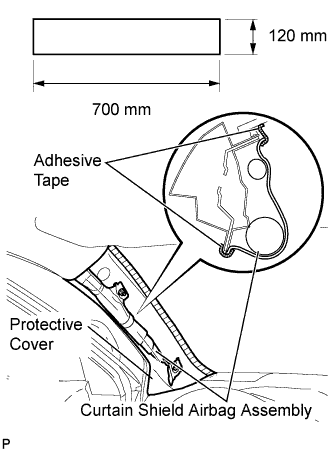
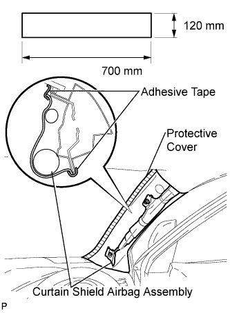
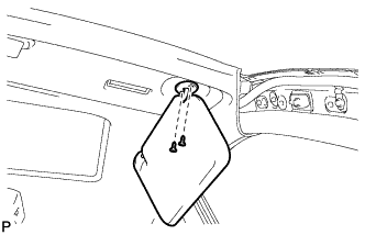
Protect the curtain shield airbag assembly.
-
Cover the airbag with a 700 mm (27.56 in.) x 120 mm (4.72 in.) cloth or piece of nylon and fix the ends of the cover with tape, as shown in the illustration.
Note
Cover the curtain shield airbag with a protective cover as soon as the front pillar garnish is removed.
-
-
-
REMOVE REAR DOOR SCUFF PLATE LH
-
Disengage the 5 claws, 3 clips and guide, and remove the rear door scuff plate LH.
-
-
REMOVE REAR DOOR OPENING TRIM WEATHERSTRIP LH
-
Remove the rear door opening trim weatherstrip LH.
-
-
REMOVE FRONT DOOR SCUFF PLATE RH
Tech Tips
Use the same procedure for the RH side and the LH side.
-
REMOVE COWL SIDE TRIM SUB-ASSEMBLY RH
Tech Tips
Use the same procedure for the RH side and the LH side.
-
REMOVE FRONT DOOR OPENING TRIM WEATHERSTRIP RH
Tech Tips
Use the same procedure for the RH side and the LH side.
-
REMOVE FRONT PILLAR GARNISH RH
-
Pull the upper part of the garnish toward the inside of the cabin and disengage the 2 clips.
-
Cut off the clip <A>.
-
Disengage the 3 guides and remove the front pillar garnish RH.
-
Remove the clip <A>.
-
Protect the curtain shield airbag assembly.
-
Cover the airbag with a 700 mm (27.56 in.) x 120 mm (4.72 in.) cloth or piece of nylon and fix the ends of the cover with tape, as shown in the illustration.
Note
Cover the curtain shield airbag with a protective cover as soon as the front pillar garnish is removed.
-
-
-
REMOVE REAR DOOR SCUFF PLATE RH
Tech Tips
Use the same procedure for the RH side and the LH side.
-
REMOVE REAR DOOR OPENING TRIM WEATHERSTRIP RH
Tech Tips
Use the same procedure for the RH side and the LH side.
-
REMOVE LOWER CENTER PILLAR GARNISH LH
-
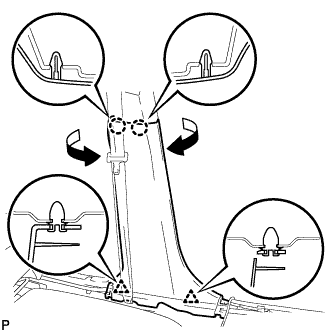
Disengage the 2 claws and 2 clips, and remove the lower center pillar garnish LH.
-
-
DISCONNECT FRONT SEAT OUTER BELT ASSEMBLY LH
-
Remove the bolt and disconnect the floor end of the front seat outer belt assembly.
-
-
REMOVE CENTER PILLAR GARNISH LH
-
Remove the screw and clip.
-
Disengage the 2 guides and clip, and remove the center pillar garnish LH.
-
-
REMOVE LOWER CENTER PILLAR GARNISH RH
Tech Tips
Use the same procedure for the RH side and the LH side.
-
DISCONNECT FRONT SEAT OUTER BELT ASSEMBLY RH
Tech Tips
Use the same procedure for the RH side and the LH side.
-
REMOVE CENTER PILLAR GARNISH RH
Tech Tips
Use the same procedure for the RH side and the LH side.
-
REMOVE DECK BOARD ASSEMBLY
-
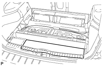
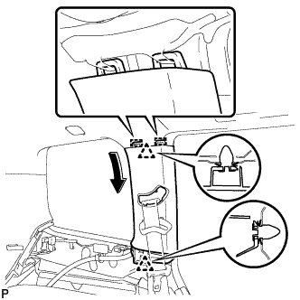
Remove the deck board assembly.
-
-
REMOVE NO. 3 DECK BOARD SUB-ASSEMBLY
-
Disengage the 2 guides and remove the No. 3 deck board sub-assembly.
-
-
REMOVE NO. 2 DECK BOARD SUB-ASSEMBLY
-
Disengage the 2 guides and remove the No. 2 deck board sub-assembly.
-
-
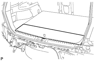
REMOVE TONNEAU COVER ASSEMBLY (w/ Tonneau Cover)
-
Remove the tonneau cover assembly.
-
-
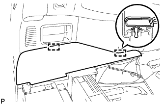
REMOVE REAR NO. 1 FLOOR BOARD (w/o Rear No. 2 Seat)
-
Disengage the 3 clips and the 3 guides, and remove the rear No. 1 floor board.
-
-
REMOVE REAR SEAT SIDE COVER LH (w/ Rear No. 2 Seat)
-
Disengage the 2 clips and remove the rear seat side cover LH.
-
-
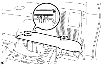
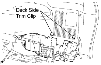
REMOVE DECK SIDE TRIM BOX LH
-
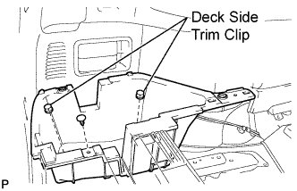
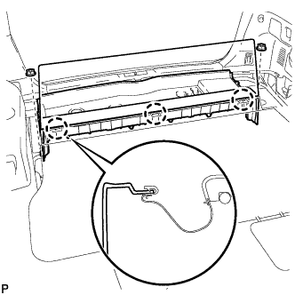
Remove the 2 deck side trim clips and clip.
-
Remove the deck side trim box LH as shown in the illustration.
-
-
REMOVE REAR SEAT SIDE COVER RH (w/ Rear No. 2 Seat)
-
Disengage the 2 clips and remove the rear seat side cover RH.
-
-
REMOVE JACK CARRIER SUPPORT
-
REMOVE JACK CARRIER CUSHION (for LHD)
-
Remove the jack carrier cushion.
-
-
REMOVE JACK CARRIER CUSHION (for RHD)
-

Remove the jack carrier cushion.
-
-
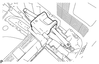
REMOVE JACK ASSEMBLY (for LHD)
-
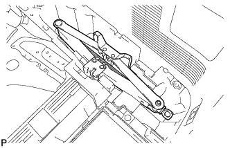
Remove the jack assembly.
-
-
REMOVE JACK ASSEMBLY (for RHD)
-
Remove the jack assembly.
-
-
REMOVE JACK CARRIER ASSEMBLY (for LHD)
-
Using a screwdriver, disengage the 3 claws and remove the jack carrier assembly.
-
-
REMOVE JACK CARRIER ASSEMBLY (for RHD)
-
Using a screwdriver, disengage the 3 claws and remove the jack carrier assembly.
-
-
REMOVE DECK SIDE TRIM BOX RH
-
Remove the 2 deck side trim clips and clip.
-
Remove the deck side trim box RH as shown in the illustration.
-
-
REMOVE DECK FLOOR BOARD ASSEMBLY (w/o Rear No. 2 Seat)
-
Remove the 4 bolts and 4 nuts.
-
Remove the deck floor board assembly.
-
-
REMOVE REAR MAT
-
Remove the rear mat.
-
-
REMOVE DECK FLOOR BOARD ASSEMBLY (w/ Rear No. 2 Seat)
-
Disengage the 3 claws.
-
Remove the 2 nuts and the deck floor board assembly.
-
-
REMOVE REAR DECK FLOOR BOX (w/o Rear No. 2 Seat)
-
Remove the 2 nuts and the deck floor box.
-
-
REMOVE NO. 1 DECK BOARD (w/o Rear No. 2 Seat)
-
Disengage the 3 clips and remove the rear floor board spacer from No. 1 deck board.
-
-
REMOVE NO. 1 DECK BOARD (w/ Rear No. 2 Seat)
-
Disengage the 5 clips and remove the rear deck floor box from the No. 1 deck board.
-
-
REMOVE REAR NO. 2 SEAT INNER BELT ASSEMBLY (w/ Rear No. 2 Seat)
-
Remove the bolt and rear No. 2 seat inner belt assembly.
Tech Tips
Use the same procedure for the RH side and LH side.
-
-
DISCONNECT REAR SEAT LAP TYPE BELT ASSEMBLY LH (w/ Rear No. 2 Seat)
-
Remove the bolt and disconnect the rear seat lap type belt assembly LH.
-
-
DISCONNECT REAR SEAT LAP TYPE BELT ASSEMBLY RH (w/ Rear No. 2 Seat)
Tech Tips
Use the same procedure for the RH side and the LH side.
-
REMOVE REAR NO. 2 SEAT ASSEMBLY (w/ Rear No. 2 Seat)
-
Remove the 4 bolts and the rear No. 2 seat assembly.
-
-
REMOVE REAR FLOOR FINISH PLATE
-
Disengage the 4 clips and the 4 claws, and remove the rear floor finish plate.
-
-
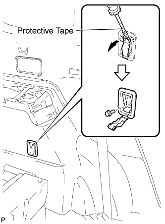
REMOVE DECK SIDE TRIM COVER NO.2
-
Using a screwdriver, disengage the 2 claws and remove the deck side trim cover LH.
Tech Tips
Tape the screwdriver tip before use.
-
-
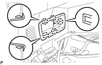
REMOVE DECK SIDE TRIM LH
-
Remove the bolt.
-
Disengage the 4 claws and the 3 guides, and remove the deck side trim LH as shown in the illustration.
-
-
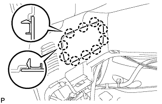
REMOVE SIDE TRIM COVER LH
-
Disengage the 10 claws and remove the side trim cover LH.
-
-
REMOVE REAR COMBINATION LIGHT SERVICE COVER LH
-

Using a screwdriver, disengage the 6 claws and 2 guides, and remove the rear combination light service cover LH.
Tech Tips
Tape the screwdriver tip before use.
-
-
REMOVE REAR POWER POINT SOCKET ASSEMBLY
-
Disconnect the connector.
-
Disengage the claw and remove the rear power point socket assembly.
-
-
REMOVE REAR POWER OUTLET SOCKET COVER
-
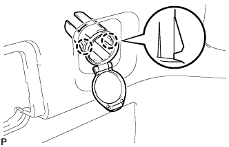
Disengage the 2 claws and remove the rear power outlet socket cover.
-
-
REMOVE REAR DECK TRIM COVER (w/o Remote Folding Function)
-
Disengage the 10 claws and remove the rear deck trim cover.
-
-
REMOVE RECLINING REMOTE CONTROL LEVER BEZEL LH (w/ Remote Folding Function)
-
Disengage the 5 claws and remove the reclining remote control bezel LH.
-
-
REMOVE ROPE HOOK ASSEMBLY (for LH Side)
-
for Front Side:
-
Using a screwdriver, disengage the 2 claws.
Tech Tips
Tape the screwdriver tip before use.
-
Remove the bolt and the rope hook assembly.
-
-
for Rear Side:
-
Using a screwdriver, disengage the 2 claws.
Tech Tips
Tape the screwdriver tip before use.
-
Remove the bolt and rope hook assembly.
-
-
-
REMOVE NO. 2 DECK SIDE TRIM HOOK
-
Remove the screw and the No. 2 deck side trim hook.
-
-
REMOVE FRONT DECK SIDE TRIM COVER LH
-
Using a screwdriver, disengage the 4 claws and remove the 2 front deck side trim covers LH.
Tech Tips
Tape the screwdriver tip before use.
-
-
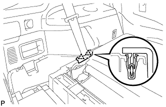
DISCONNECT REAR NO. 1 SEAT OUTER BELT ASSEMBLY LH
-
Remove the bolt and disconnect the floor end of the rear No. 1 seat outer belt assembly.
-
-
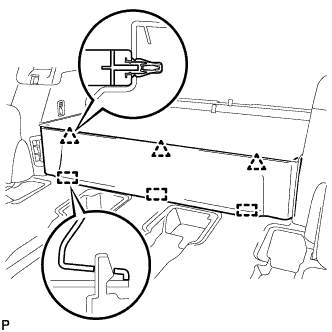
REMOVE DECK TRIM SIDE PANEL ASSEMBLY LH
-
Remove the 2 bolts.
-
Remove the 2 clips.
-
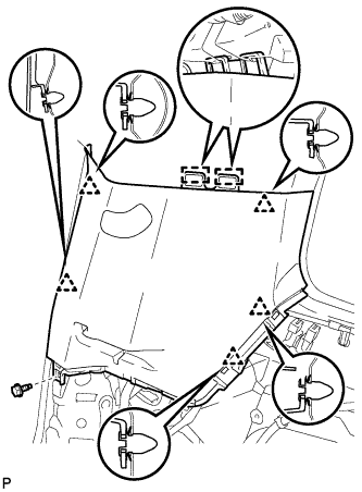
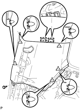
Disengage the 7 claws and 4 clips, and remove the deck trim side panel assembly LH.
-
-
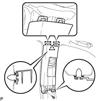
REMOVE QUARTER PILLAR GARNISH LH
-
Disengage the 2 claws and 2 guides, and remove the No. 1 seat outer belt guide.
-
Disengage the 2 clips and the 2 guides, and remove the quarter pillar garnish LH.
-
-
REMOVE ROOF SIDE INNER GARNISH ASSEMBLY LH (w/o Power Back Door)
-
w/o Rear No. 2 Seat:
-
Remove the bolt.
-
Disengage the 5 clips and 2 guides, and remove the roof side inner garnish assembly LH.
-
-
w/ Rear No. 2 Seat:
-
Disengage the 2 claws and 2 guides, and remove the rear No. 2 seat outer belt guide.
-
Remove the bolt.
-
Disengage the 5 clips and 2 guides, and remove the roof side inner garnish assembly LH.
-
-
-
REMOVE ROOF SIDE INNER GARNISH ASSEMBLY LH (w/ Power Back Door)
-
w/o Rear No. 2 Seat:
-
Remove the bolt.
-
Disengage the 5 clips and 2 guides, and remove the roof side inner garnish assembly LH.
-
-
w/ Rear No. 2 Seat:
-
Disengage the 2 claws and 2 guides, and remove the rear No. 2 seat outer belt guide.
-

Remove the bolt.
-
Disengage the 5 clips and 2 guides, and remove the roof side inner garnish assembly LH.
-
-
-
REMOVE REAR SEAT SIDE GARNISH CAP (w/o Rear Air Conditioning System)
-
Disengage the 8 claws and guide, and remove the rear seat side garnish cap.
-
-
REMOVE REAR SEAT SIDE GARNISH CAP (w/ Rear Air Conditioning System)
-
Remove the screw.
-
Disengage the 6 claws and the guide, and remove the rear seat side garnish cap.
-
-
REMOVE DECK SIDE TRIM COVER NO.1
Tech Tips
Use the same procedure for the RH side and the LH side.
-
REMOVE DECK SIDE TRIM RH
Tech Tips
Use the same procedure for the RH side and the LH side.
-
REMOVE SIDE TRIM COVER RH (w/o Rear Automatic Air Conditioning System)
-
Disengage the 4 claws and remove the side trim cover RH.
-
-
REMOVE REAR ROOM TEMPERATURE SENSOR (w/ Rear Automatic Air Conditioning System)
-
Disengage the 4 claws and remove the rear room temperature sensor.
-
Disconnect the connector.
-
-
REMOVE REAR COMBINATION LIGHT SERVICE COVER RH
-
Using a screwdriver, disengage the 6 claws and the 2 guides, and remove the rear combination light service cover RH.
Tech Tips
Tape the screwdriver tip before use.
-
-
REMOVE ROPE HOOK ASSEMBLY (for RH Side)
Tech Tips
Use the same procedure for the RH side and the LH side.
-
REMOVE NO. 1 LUGGAGE COMPARTMENT TRIM HOOK
Tech Tips
Use the same procedure for the No. 1 luggage compartment trim hook and the No. 2 deck side trim hook.
-
REMOVE FRONT DECK SIDE TRIM COVER RH
Tech Tips
Use the same procedure for the RH side and the LH side.
-
DISCONNECT REAR NO. 1 SEAT OUTER BELT ASSEMBLY RH
Tech Tips
Use the same procedure for the RH side and the LH side.
-
REMOVE DECK TRIM SIDE PANEL ASSEMBLY RH
-
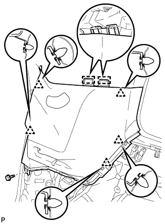
Remove the 3 bolts.
-
Remove the 2 clips.
-
Disengage the 7 claws and 4 clips, and remove the deck trim side panel assembly RH.
-
-
REMOVE QUARTER PILLAR GARNISH RH
Tech Tips
Use the same procedure for the RH side and the LH side.
-
REMOVE ROOF SIDE INNER GARNISH ASSEMBLY RH (w/o Rear No. 2 Seat)
Tech Tips
Use the same procedure for the RH side and the LH side.
-
REMOVE ROOF SIDE INNER GARNISH ASSEMBLY RH (w/ Rear No. 2 Seat)
Tech Tips
Use the same procedure for the RH side and the LH side.
-
REMOVE ROOF CONSOLE BOX ASSEMBLY
-

Using a moulding remover, disengage the 2 clips, 3 guides and fastener.
-
Disconnect the connector and remove the roof console box assembly.
-
-
REMOVE VISOR BRACKET COVER (for LH Side)
-
Using a moulding remover, disengage the 4 claws and remove the visor bracket cover.
-
-
REMOVE VISOR ASSEMBLY LH
-
Remove the 2 screws and remove the visor assembly LH.
-
-
REMOVE VISOR BRACKET COVER (for RH Side)
Tech Tips
Use the same procedure for the RH side and the LH side.
-
REMOVE VISOR ASSEMBLY RH
Tech Tips
Use the same procedure for the RH side and the LH side.
-
REMOVE INNER REAR VIEW MIRROR STAY HOLDER COVER (w/ EC Mirror)
-
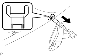
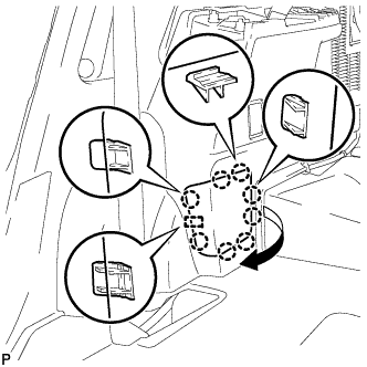
Disengage the 2 claws and slide the inner rear view mirror stay holder cover as shown in the illustration.
-
Disengage the 2 claws and remove the inner rear view mirror stay holder cover.
-
-
REMOVE NO. 1 ROOM LIGHT ASSEMBLY (for Standard)
-
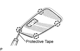
Using a screwdriver, disengage the 4 claws and remove the lens cover.
Tech Tips
Tape the screwdriver tip before use.
-
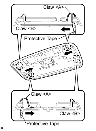
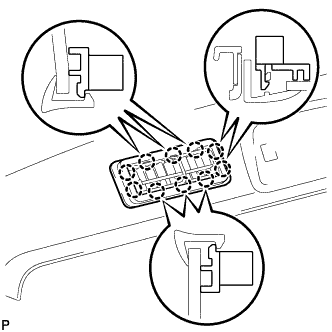
Using a screwdriver, disengage the 2 claws <A> as shown in the illustration.
Tech Tips
Tape the screwdriver tip before use.
-
Disengage the 2 claws <B>.
-
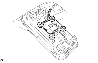
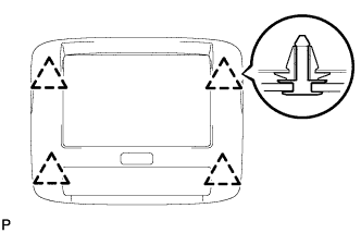
Using a screwdriver, disengage the 4 claws and remove the No. 1 room light assembly.
-
-
REMOVE NO. 1 ROOM LIGHT ASSEMBLY (for Independent Type)
-
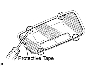
Using a screwdriver, disengage the 4 claws and remove the lens cover.
Tech Tips
Tape the screwdriver tip before use.
-
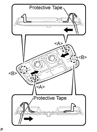
Using a screwdriver, disengage the 2 claws <A> as shown in the illustration.
Tech Tips
Tape the screwdriver tip before use.
-
Disengage the 2 claws <B>.
-
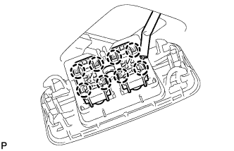
Using a screwdriver, disengage the 8 claws and remove the No. 1 room light assembly.
-
-
REMOVE NO. 2 ROOM LIGHT ASSEMBLY
-
Using a screwdriver, disengage the 4 claws and remove the lens cover.
Tech Tips
Tape the screwdriver tip before use.
-
Using a screwdriver, disengage the 2 claws <A> as shown in the illustration.
Tech Tips
Tape the screwdriver tip before use.
-
Disengage the 2 claws <B>.
-
Using a screwdriver, disengage the 4 claws and remove the No. 2 room light assembly.
-
-
REMOVE TELEVISION BASE (w/ Rear Seat Entertainment System)
-
Disengage the 4 clips and remove the television base.
-
-
REMOVE TELEVISION DISPLAY ASSEMBLY (w/ Rear Seat Entertainment System)
-
Disconnect the connector.
-
Remove the 4 bolts.
-
Disengage the 2 clips and 2 claws, and then remove the television display.
-
-
REMOVE FRONT ASSIST GRIP SUB-ASSEMBLY (w/o Sliding Roof)
-
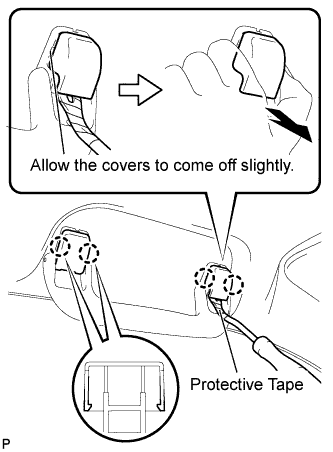
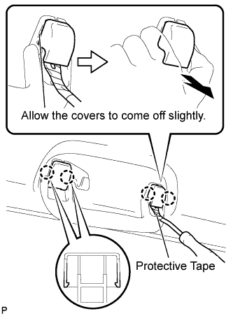
Using a clip remover, disengage the 4 claws.
Note
Do not forcibly pry the assist grip covers to prevent them from being deformed.
Tech Tips
-
Gently pry on the assist grip covers as shown in the illustration to remove them.
-
Tape the clip remover tip before use.
-
-
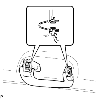
Pull off the 2 assist grip covers by hand.
-
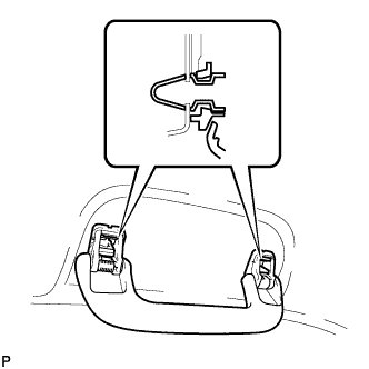
Disengage the 2 clips and remove the front assist grip sub-assembly.
-
Remove the 2 clips from the vehicle body.
Tech Tips
Use the same procedure for the RH side and the LH side.
-
-
REMOVE REAR ASSIST GRIP SUB-ASSEMBLY (w/o Sliding Roof)
-
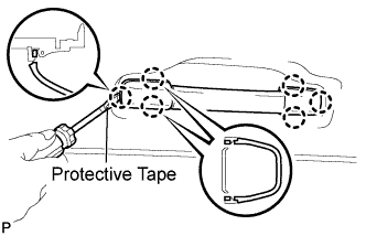
Using a clip remover, disengage the 4 claws.
Note
Do not forcibly pry the assist grip covers to prevent them from being deformed.
Tech Tips
-
Gently pry on the assist grip covers as shown in the illustration to remove them.
-
Tape the clip remover tip before use.
-
-
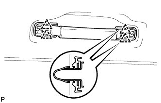
Pull off the 2 assist grip covers by hand.
-
Disengage the 2 clips and remove the rear assist grip sub-assembly.
-
Remove the 2 clips from the vehicle body.
Tech Tips
Use the same procedure for the RH side and the LH side.
-
-
REMOVE ASSIST GRIP ASSEMBLY (w/ Sliding Roof)
-
Using a screwdriver, disengage the 6 claws and remove the 2 assist grip covers.
Note
Do not forcibly pry the assist grip covers to prevent them from being deformed.
Tech Tips
Tape the screwdriver tip before use.
-
Disengage the 4 clips and remove the assist grip assembly.
-
Remove the 4 clips from the vehicle body.
Tech Tips
Use the same procedure for the other 4 assist grips.
-
-
REMOVE ROOF HEADLINING TRIM CLIP STOPPER
-
Using a screwdriver, disengage the 3 claws.
Tech Tips
Tape the screwdriver tip before use.
-
Remove the bolt and the roof headlining trim clip stopper.
Tech Tips
Use the same procedure for the RH side and the LH side.
-
-
REMOVE SUN ROOF OPENING TRIM MOULDING (w/ Sliding Roof)
-
REMOVE VISOR HOLDER
-
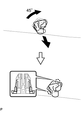
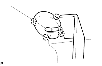
Turn the visor holder approximately 45° and pull it out as shown in the illustration.
-
Disengage the 2 claws and remove the visor holder.
Tech Tips
Use the same procedure for the RH side and the LH side.
-
-
REMOVE ROOF HEADLINING ASSEMBLY (w/o Sliding Roof)
-
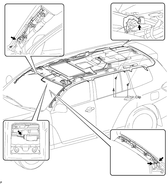
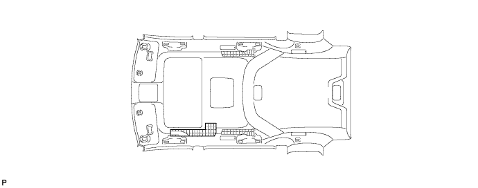
Disconnect the No. 1 roof wire connector and disengage the 3 clamps from the front pillar LH.
-
Disconnect the No. 2 antenna cord sub-assembly connector, disengage the 3 clamps, and remove the bolt from the front pillar RH.
-
Disconnect the No. 2 antenna cord sub-assembly connector from the rear pillar RH.
-
Remove the 4 clips.
-
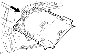
Remove the roof headlining assembly from the vehicle through the back door.
Note
Do not damage the roof headlining assembly or body interior.
-
-
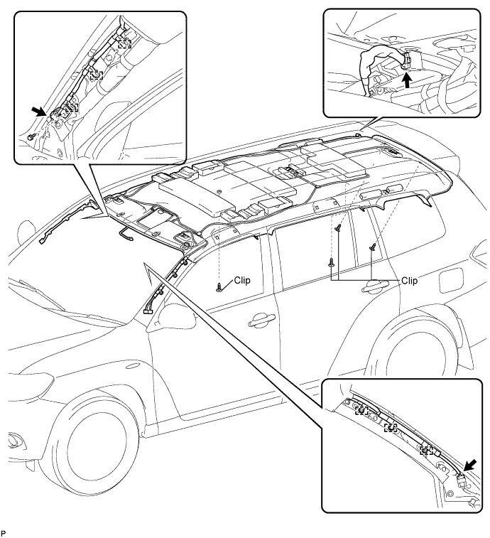
REMOVE ROOF HEADLINING ASSEMBLY (w/ Sliding Roof)
-
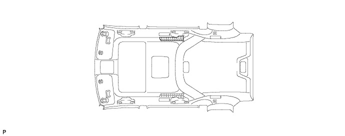
Disconnect the No. 1 roof wire connectors and disengage the 3 clamps from the front pillar LH.
-
w/ Rear Seat Entertainment System:
-
Disconnect the No. 1 roof wire connector from the rear pillar LH.
-
-
Disconnect the No. 2 antenna cord sub-assembly connector, disengage the 3 clamps and remove the bolt from the front pillar RH.
-
Disconnect the No. 2 antenna cord sub-assembly connector from the rear pillar RH.
-
Disconnect the sliding roof drive gear connector.
-
Remove the 3 clips.
-
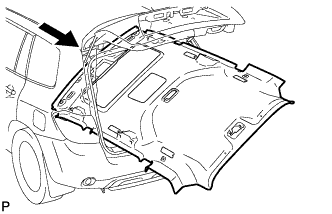
Remove the roof headlining assembly from the vehicle through the back door.
Note
Do not damage the roof headlining assembly or body interior.
-
-
REMOVE VANITY LIGHT ASSEMBLY (w/ Vanity Light)
-
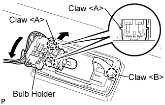
Disengage the 2 claws <A> and separate the bulb holder from the vanity light assembly as shown in the illustration.
-
Disengage the claw <B> and remove the vanity light assembly.
Tech Tips
Use the same procedure to remove the light on the other side.
-
-
REMOVE FRONT SIDE RAIL SPACER LH (w/o Sliding Roof)
-
Remove the front side rail spacer LH.
-
-
REMOVE FRONT SIDE RAIL SPACER RH (w/o Sliding Roof)
Tech Tips
Use the same procedure for the RH side and the LH side.
-
REMOVE REAR NO. 2 SIDE RAIL SPACER LH (w/o Sliding Roof)
-
Remove the rear No. 2 side rail spacer LH.
-
-
REMOVE REAR NO. 2 SIDE RAIL SPACER RH (w/o Sliding Roof)
Tech Tips
Use the same procedure for the RH side and the LH side.
-
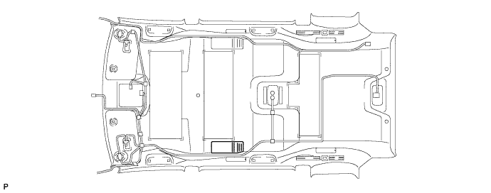
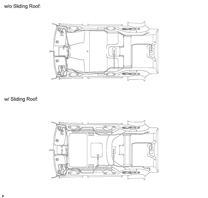
REMOVE NO. 1 ROOF SILENCER PAD (w/o Sliding Roof)
-
Remove the No. 1 roof silencer pad.
-
-
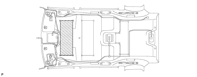
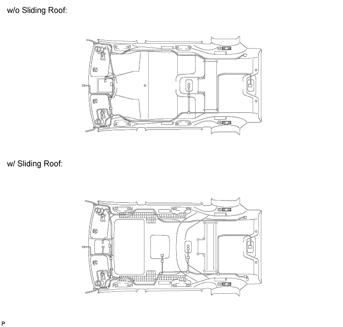
REMOVE NO. 2 ROOF SILENCER PAD (w/o Sliding Roof)
-
Remove the No. 2 roof silencer pad.
-
-
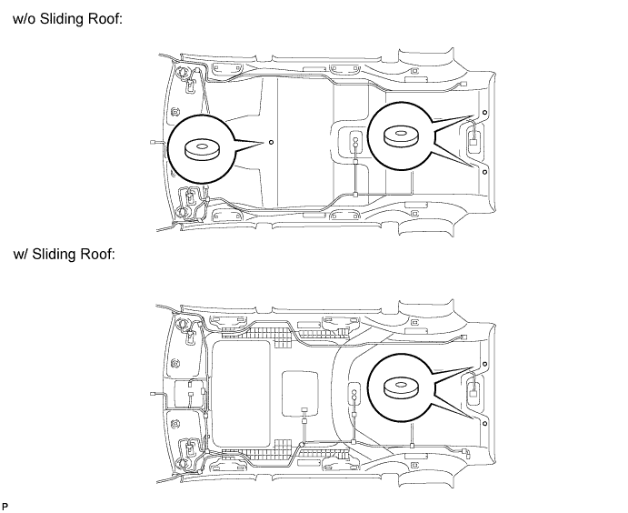
REMOVE NO. 1 ROOF HEADLINING SUPPORT
-
Remove the 2 No. 1 roof headlining supports.
-
-
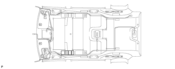
REMOVE ROOF HEADLINING PAD
-
Remove the 2 roof headlining pads.
-
-
REMOVE NO. 2 ROOF HEADLINING PAD
-
Remove the 2 No. 2 roof headlining pads.
-
-
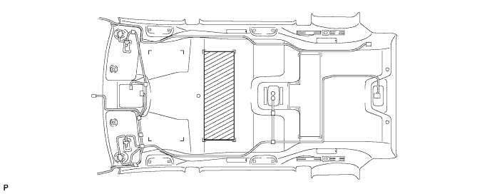
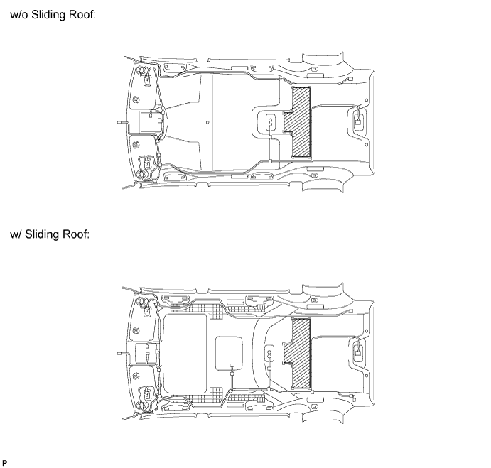
REMOVE NO. 4 ROOF SILENCER PAD
-
Remove the No. 4 roof silencer pad.
-
-
REMOVE NO. 2 ROOF HEADLINING SUPPORT
-
Remove each No. 2 roof headlining support.
-
-
REMOVE NO. 1 AIR OUTLET REGISTER ASSEMBLY (w/ Rear Air Conditioning System)
-
Disengage the 10 claws, and remove the No. 1 air outlet register assembly from the roof side outlet register.
-
-
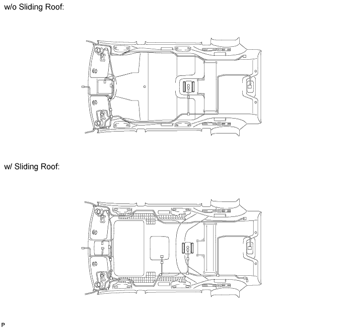
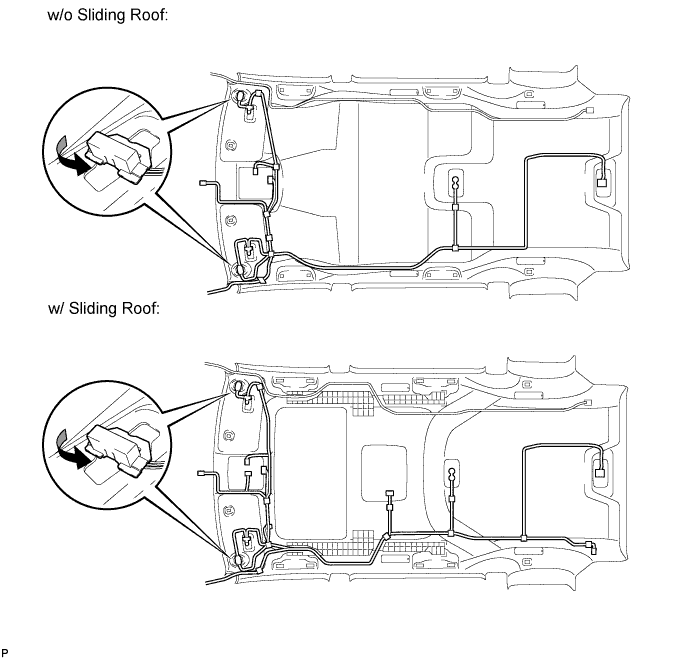
REMOVE NO. 1 ROOF WIRE
-
w/ Vanity Light:
-
Turn the visor connectors counterclockwise approximately 90° and disconnect the connectors from the roof headlining assembly.
-
-
Remove the No. 1 roof wire from the roof headlining assembly.
-
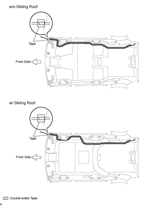
Remove the double-sided tape from the roof headlining assembly.
-
-
REMOVE NO. 2 ANTENNA CORD SUB-ASSEMBLY
-
Peel the strips of the tape used to secure the antenna cord only to the extent that allows removal of the antenna cord.
Tech Tips
Tape is not available as a supply part. Try to leave as much tape as possible on the roof headlining so that the tape can be reused.
-
Remove the No. 2 antenna cord sub-assembly from the roof headlining.
-
-
REMOVE ROOF SIDE RAIL GARNISH PAD RH (w/ Sliding Roof)
-
Remove the roof side rail garnish pad RH.
-
-
REMOVE ROOF SIDE RAIL GARNISH PAD LH (w/ Sliding Roof)
-
Remove the roof side rail garnish pad LH.
-
-
REMOVE REAR ROOF SIDE RAIL PAD RH (w/ Sliding Roof)
-
Remove the rear roof side rail pad RH.
-
-
REMOVE REAR ROOF SIDE RAIL PAD LH (w/ Sliding Roof)
-
Remove the rear roof side rail pad LH.
-