- Click here
INSTALL BACK DOOR CLOSER NO. 1 GEAR
-
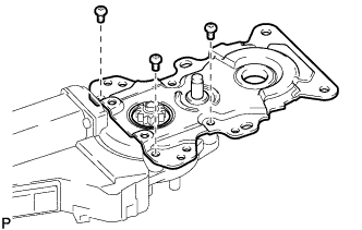
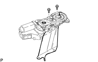
Install a new power back door case sub-assembly with 3 new screws.
2.0 N*m 20 kgf*cm 18 in.*lbf -
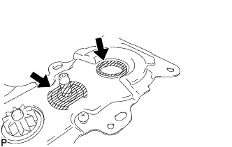
Apply power back door grease to the sliding parts of the power back door case sub-assembly.
-
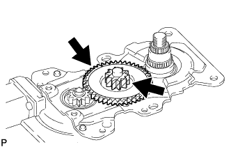
Install the power back door No. 3 shaft as shown in the illustration.
Note:Make sure not to apply power back door grease to the threads of the power back door No. 3 shaft to avoid the nut of the power back door arm sub-assembly from becoming loose.
-
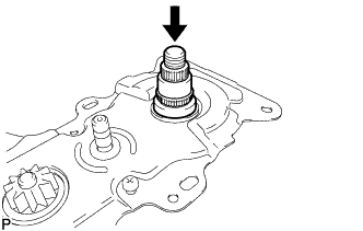
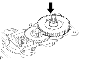
Install a mew new power back door gear sub-assembly as shown in the illustration.
Note:Make sure not to apply power back door grease to the threads of the power back door No. 3 shaft to avoid the nut of the power back door arm sub-assembly from becoming loose.
-
Apply power back door grease to the sliding parts of the new power back door gear sub-assembly.
-
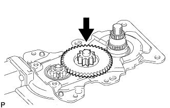
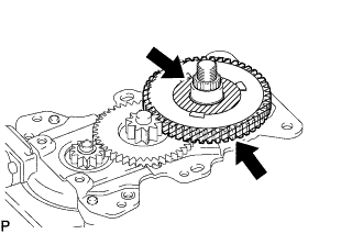
Install the power back door No. 4 gear as shown in the illustration.
Note:Make sure not to apply power back door grease to the threads of the power back door No. 3 shaft to avoid the nut of the power back door arm sub-assembly from becoming loose.
-
Apply power back door grease to the sliding parts of the power back door No. 4 gear.
-
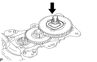
Install the power back door wave washer as shown in the illustration.
Note:Make sure not to apply power back door grease to the threads of the power back door No. 3 shaft to avoid the nut of the power back door arm sub-assembly from becoming loose.
-
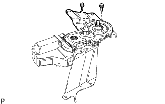
Install the power back door bracket sub-assembly with 2 new bolts.
13 N*m 127 kgf*cm 9 ft.*lbf -
Install the power back door bracket sub-assembly with 2 new bolts.
13 N*m 127 kgf*cm 9 ft.*lbf -
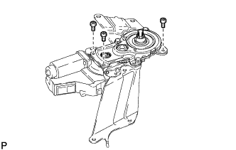
Install power back door case sub-assembly with 3 new screws.
2.0 N*m 20 kgf*cm 18 in.*lbf
-
- Click here
INSTALL BACK DOOR UPPER ROD
-
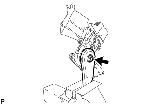
Clamp a new power back door arm sub-assembly in a vise between aluminum plates.
74 N*m 754 kgf*cm 55 ft.*lbf -
Install the power back door arm sub-assembly with a new nut.
-
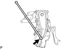
Attach the ball joint to install a new power back door rod.
-