BACK DOOR ADJUSTMENT
Tech Tips
-
Use the same procedure for the RH side and LH side.
-
The following procedure is for the LH side.
-
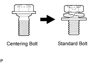
Centering bolts are used to mount the door hinge to the vehicle body and door. The door cannot be adjusted with the centering bolts installed. Substitute the centering bolts with standard bolts (with washers) when making adjustments.
-
A bolt without a torque specification is shown in the standard bolt chart Click here.
-
PRECAUTION
Note
-
For the glass hatch type, if the back door adjustment is performed, the location of the axis of the rear wiper motor assembly will change, causing the wiping angle to change. Be sure to remove and install the rear wiper motor assembly using the centering jig.
-
Do not open the glass hatch before installing the rear wiper link pivot.
-
-
REMOVE DECK BOARD ASSEMBLY
-
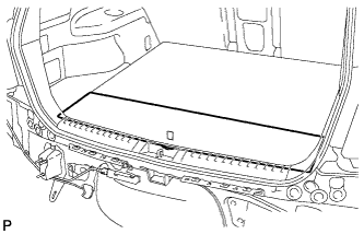
Remove the deck board assembly.
-
-
REMOVE NO. 3 DECK BOARD SUB-ASSEMBLY
-
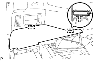
Disengage the 2 guides and remove the No. 3 deck board sub-assembly.
-
-
REMOVE NO. 2 DECK BOARD SUB-ASSEMBLY
-
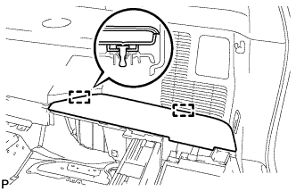
Disengage the 2 guides and remove the No. 2 deck board sub-assembly.
-
-
REMOVE TONNEAU COVER ASSEMBLY (w/ Tonneau Cover)
-
Remove the tonneau cover assembly.
-
-
REMOVE REAR NO. 1 FLOOR BOARD (w/o Rear No. 2 Seat)
-
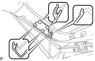
Disengage the 3 clips and 3 guides, and remove the rear No. 1 floor board.
-
-
REMOVE REAR SEAT SIDE COVER LH (w/ Rear No. 2 Seat)
-
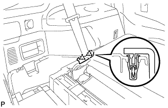
Disengage the 2 clips and remove the rear seat side cover LH.
-
-
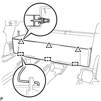
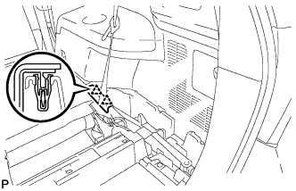
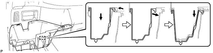
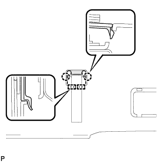
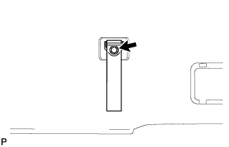
REMOVE DECK SIDE TRIM BOX LH
-
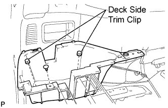
Remove the 2 deck side trim clips and clip.
-
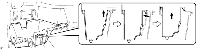
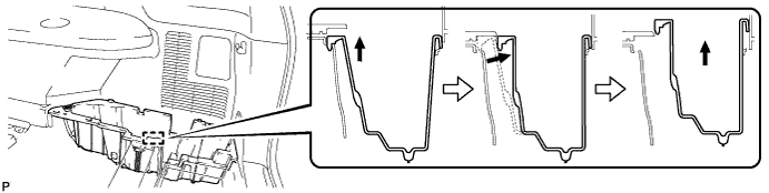
Remove the deck side trim box LH as shown in the illustration.
-
-
REMOVE REAR SEAT SIDE COVER RH (w/ Rear No. 2 Seat)
-
Disengage the 2 clips and remove the rear seat side cover RH.
-
-
REMOVE JACK CARRIER SUPPORT
-
REMOVE JACK CARRIER CUSHION (for LHD)
-
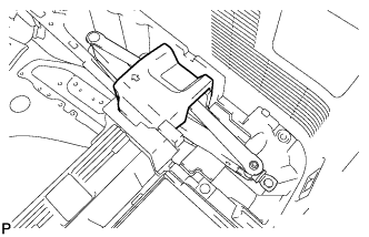
Remove the jack carrier cushion.
-
-
REMOVE JACK CARRIER CUSHION (for RHD)
-

Remove the jack carrier cushion.
-
-
REMOVE JACK ASSEMBLY (for LHD)
-
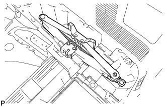
Remove the jack assembly.
-
-
REMOVE JACK ASSEMBLY (for RHD)
-
Remove the jack assembly.
-
-
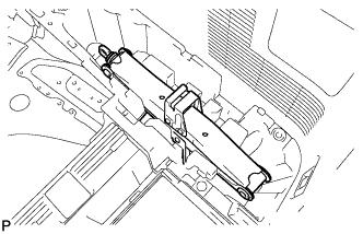
REMOVE JACK CARRIER ASSEMBLY (for LHD)
-
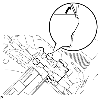
Using a screwdriver, disengage the 3 claws and remove the jack carrier assembly.
-
-
REMOVE JACK CARRIER ASSEMBLY (for RHD)
-
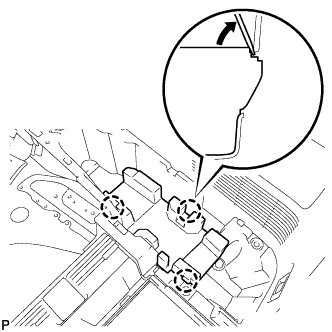
Using a screwdriver, disengage the 3 claws and remove the jack carrier assembly.
-
-
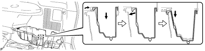
REMOVE DECK SIDE TRIM BOX RH
-
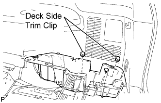
Remove the 2 deck side trim clips and clip.
-
Remove the deck side trim box RH as shown in the illustration.
-
-
REMOVE DECK FLOOR BOARD ASSEMBLY (w/o Rear No. 2 Seat)
-
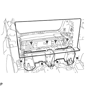
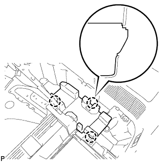
Remove the 4 bolts and 4 nuts.
-
Remove the deck floor board assembly.
-
-
REMOVE REAR MAT
-
Remove the rear mat.
-
-
REMOVE DECK FLOOR BOARD ASSEMBLY (w/ Rear No. 2 Seat)
-

Disengage the 3 claws.
-
Remove the 2 nuts and deck floor board assembly.
-
-
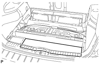
REMOVE REAR DECK FLOOR BOX (w/o Rear No. 2 Seat)
-
Remove the 2 nuts and the deck floor box.
-
-
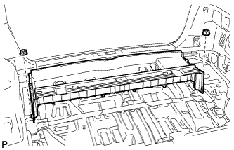
REMOVE REAR FLOOR FINISH PLATE
-
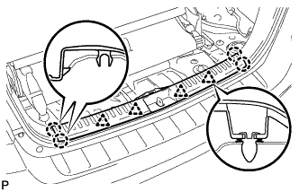
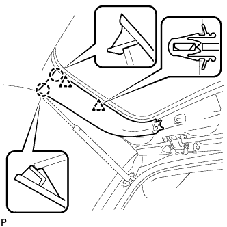
Disengage the 4 clips and 4 claws, and remove the rear floor finish plate.
-
-
ADJUST BACK DOOR PANEL SUB-ASSEMBLY
-
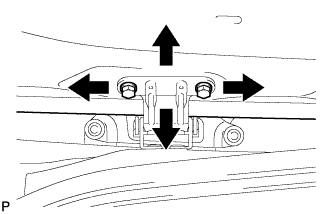
Before adjusting the upper end of the back door up and down or left and right, loosen the bolts.
-
Tighten the body side hinge after the adjustment.
- Torque:
- 20 N*m { 204 kgf*cm, 15 ft.*lbf }
-
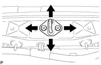
Adjust the striker position by slightly loosening the striker mounting screws and hitting the striker with a plastic hammer.
-
Tighten the striker mounting screws after the adjustment.
- Torque:
- 23 N*m { 235 kgf*cm, 17 ft.*lbf }
-
-
INSTALL REAR FLOOR FINISH PLATE
-
Engage the 4 clips and 4 claws, and install the rear floor finish plate.
-
-
INSTALL REAR DECK FLOOR BOX (w/o Rear No. 2 Seat)
-
Install the rear deck floor box with the 2 nuts.
-
-
INSTALL DECK FLOOR BOARD ASSEMBLY (w/o Rear No. 2 Seat)
-
Install the 2 nuts and deck floor board assembly.
-
Engage the 3 claws.
-
-
INSTALL REAR MAT
-
Install the rear mat.
-
-
INSTALL DECK FLOOR BOARD ASSEMBLY (w/ Rear No. 2 Seat)
-
Install the rear deck floor board assembly with the 4 nuts and 4 bolts.
-
-
INSTALL DECK SIDE TRIM BOX LH
-
Install the deck side trim box LH as shown in the illustration.
-
Install the 2 deck side trim clips and clip.
-
-
INSTALL REAR SEAT SIDE COVER LH (w/ Rear No. 2 Seat)
-
Engage the 2 clips and install the rear seat side cover LH.
-
-
INSTALL DECK SIDE TRIM BOX RH
-
Install the deck side trim box RH as shown in the illustration.
-
Install the 2 deck side trim clips and clip.
-
-
INSTALL JACK CARRIER ASSEMBLY (for LHD)
-

Engage the 3 claws, and install the jack carrier assembly.
-
-
INSTALL JACK CARRIER ASSEMBLY (for RHD)
-
Engage the 3 claws, and install the jack carrier assembly.
-
-
INSTALL JACK ASSEMBLY (for LHD)
-
Install the jack assembly.
-
-
INSTALL JACK ASSEMBLY (for RHD)
-
Install the jack assembly.
-
-
INSTALL JACK CARRIER CUSHION (for LHD)
-
Install the jack carrier cushion.
-
-
INSTALL JACK CARRIER CUSHION (for RHD)
-
Install the jack carrier cushion.
-
-
INSTALL JACK CARRIER SUPPORT
-
INSTALL REAR SEAT SIDE COVER RH (w/ Rear No. 2 Seat)
-
Engage the 2 clips and install the rear seat side cover RH.
-
-
INSTALL REAR NO. 1 FLOOR BOARD (w/o Rear No. 2 Seat)
-
Engage the 3 guides and 3 clips and install the rear No. 1 floor board.
-
-
INSTALL TONNEAU COVER ASSEMBLY (w/ Tonneau Cover)
-
INSTALL NO. 2 DECK BOARD SUB-ASSEMBLY
-
Engage the 2 guides and install the No. 2 deck board sub-assembly.
-
-
INSTALL NO. 3 DECK BOARD SUB-ASSEMBLY
-
Engage the 2 guides and install the No. 3 deck board sub-assembly.
-
-
INSTALL DECK BOARD ASSEMBLY
-
Install the deck board assembly.
-
-
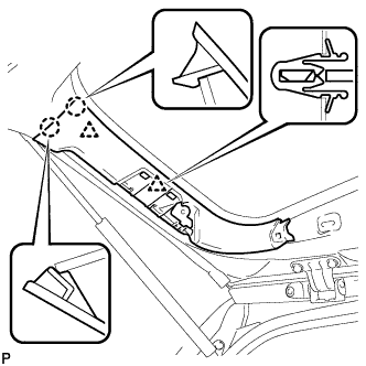
REMOVE BACK WINDOW UPPER TRIM PANEL ASSEMBLY
-
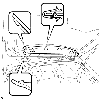
Disengage the 4 clips and 4 claws, and remove the back window upper trim panel assembly.
-
-
REMOVE BACK DOOR TRIM COVER LH (w/o Power Back Door)
-
Disengage the 2 clips and 2 claws, and remove the back door trim cover LH.
-
-
REMOVE BACK DOOR SERVICE HOLE COVER LH (w/ Power Back Door)
-
Disengage the 6 claws, and remove the back door service hole cover LH.
-
-
DISCONNECT POWER BACK DOOR ROD (w/ Power Back Door)
-
Disconnect the power back door rod and remove the back door stay plate.
-
-
REMOVE BACK DOOR TRIM COVER LH (w/ Power Back Door)
-
Disengage the 2 clips and 2 claws, and remove the back door trim cover LH.
-
-
REMOVE BACK DOOR TRIM COVER RH
-
Disengage the 2 clips and 2 claws, and remove the back door trim cover RH.
-
-
REMOVE BACK DOOR LOCK COVER (for Glass Hatch Type)
-
Disengage the 2 claws and 4 guides, and remove the back door lock cover.
-
-
REMOVE ASSIST STRAP HOLE COVER
-
Disengage the 2 claws and 2 guides, and remove the assist strap hole cover.
-
-
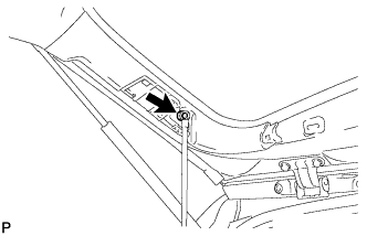
REMOVE ASSIST STRAP ASSEMBLY
-
Remove the bolt and assist strap assembly.
-
-
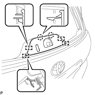
REMOVE BACK DOOR TRIM PANEL ASSEMBLY
-
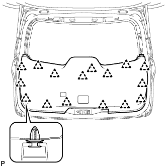
Disengage the 16 clips and remove the back door trim panel assembly.
-
-
REMOVE REAR WIPER SHAFT COVER (for Glass Hatch Type)
-
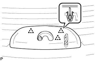
Disengage the 3 clips and remove the rear wiper shaft cover.
-
-
REMOVE REAR WIPER ARM HEAD CAP
-
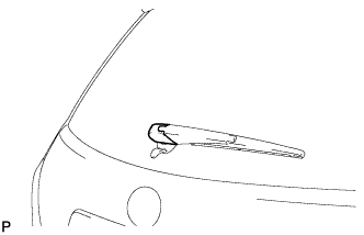
Remove the rear wiper arm head cap.
-
-
REMOVE REAR WIPER ARM AND BLADE ASSEMBLY
-
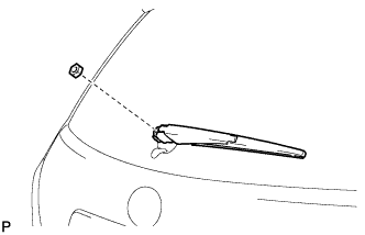
Remove the nut and the rear wiper arm and blade assembly.
-
-
REMOVE REAR WIPER LINK CAP (for Glass Hatch Type)
-
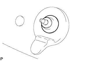
Remove the rear wiper link cap.
-
-
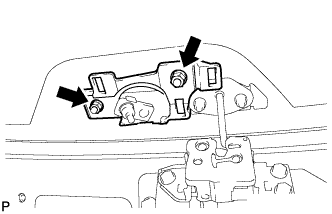
REMOVE REAR WIPER LINK PIVOT (for Glass Hatch Type)
-
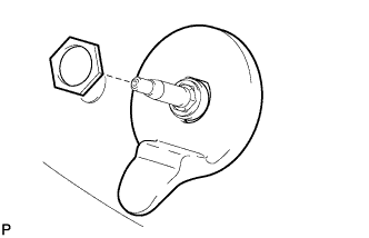
Remove the nut and the rear wiper link pivot.
-
-
REMOVE REAR WIPER MOTOR ASSEMBLY (for Glass Hatch Type)
-
When reinstalling the rear wiper motor assembly:
-
Open the glass hatch.
-
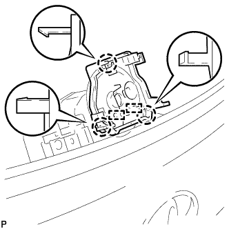
Engage the 3 claws and 2 guides, and then install the centering jig.
Note
-
The centering jig cannot be reused.
-
Do not remove the centering jig before installing the rear wiper link pivot.
-
-
Close the glass hatch, and engage the 2 claws and guide.
Note
Be sure to engage the 2 claws and guide securely.
-
Disconnect the connector.
-
Remove the 2 nuts.
-
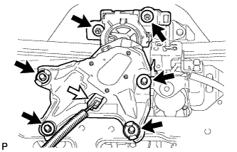
Remove the 4 bolts and the rear wiper motor assembly.
Note
-
Do not hold the rear wiper motor assembly by the rear wiper link pivot.
-
Be careful not to scratch the back door glass.
-
-
-
When using a new rear wiper motor assembly:
-
Disconnect the connector.
-
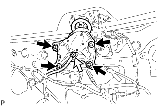
Remove the 4 bolts.
-
Remove the 2 nuts and the rear wiper motor assembly.
Note
Be careful not to scratch the back door glass.
-
-
-
INSTALL REAR WIPER MOTOR ASSEMBLY (for Glass Hatch Type)
-
Temporarily install the rear wiper motor assembly with the 4 bolts and 2 nuts.
Note
-
Do not hold the rear wiper motor assembly by the rear wiper link pivot.
-
Be careful not to scratch the back door glass.
-
Do not remove the centering jig before installing the rear wiper link pivot.
-
-
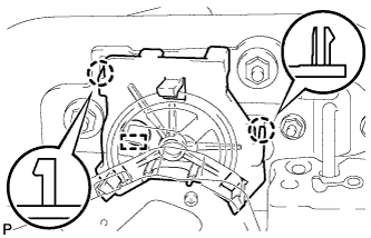
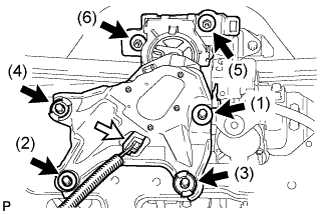
Tighten the 4 bolts and 2 nuts in the order shown in the illustration to install the rear wiper motor assembly.
- Torque:
- Bolt
- 5.5 N*m { 56 kgf*cm, 49 in.*lbf }
- Nut
- 8.0 N*m { 82 kgf*cm, 71 in.*lbf }
-
Connect the connector.
-
-
INSTALL REAR WIPER LINK PIVOT (for Glass Hatch Type)
-
Install the rear wiper link pivot with the nut.
- Torque:
- 7.0 N*m { 71 kgf*cm, 62 in.*lbf }
-
Open the glass hatch.
-
Disengage the 2 guides.
-
Disengage the 3 claws and remove the centering jig.
-
Close the glass hatch.
-
-
INSTALL REAR WIPER LINK CAP (for Glass Hatch Type)
-
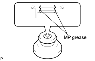
Apply MP grease to the entire surface of the rear wiper link cap.
Tech Tips
Make sure that the hole does not get clogged with grease and the grooves on the lip are filled with grease.
-
Install the rear wiper link cap.
-
-
INSTALL REAR WIPER ARM AND BLADE ASSEMBLY (for Glass Hatch Type)
-
Stop the wiper motor at the automatic stop position.
-
When reinstalling:
-
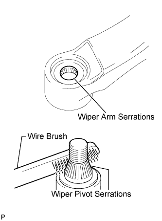
Clean the wiper arm serrations.
-
Clean the wiper pivot serrations with a wire brush.
-
-
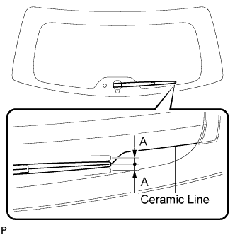
Place the rear wiper arm and blade assembly so that the rear wiper blade is aligned with the ceramic line.
Area Dimension A 10 mm (0.39 in.) -
Install the rear wiper arm and blade assembly with the nut.
- Torque:
- 5.5 N*m { 56 kgf*cm, 49 in.*lbf }
Tech Tips
Hold down the wiper arm by hand when tightening the nut.
-
-
INSTALL REAR WIPER ARM HEAD CAP
-
Install the rear wiper arm head cap.
Tech Tips
Push down on the cap until a click sound can be heard.
-
-
INSTALL REAR WIPER SHAFT COVER (for Glass Hatch Type)
-
Open the glass hatch.
-
Engage the 3 clips and install the rear wiper shaft cover.
-
Operate the rear wiper while spraying washer fluid on the glass. Make sure that the rear wiper functions properly and there is no interference with the vehicle body.
-
-
INSTALL BACK DOOR TRIM PANEL ASSEMBLY
-
Engage the 16 clips and install the back door trim panel assembly.
-
-
INSTALL ASSIST STRAP ASSEMBLY
-
Install the assist strap assembly with the bolt.
-
-
INSTALL ASSIST STRAP HOLE COVER
-
Engage the 2 guides and 2 claws, and install the assist strap hole cover.
-
-
INSTALL BACK DOOR LOCK COVER (for Glass Hatch Type)
-
Engage the 4 guides and 2 claws, and install the back door lock cover.
-
-
INSTALL BACK DOOR TRIM COVER LH (w/o Power Back Door)
-
Engage the 2 clips and 2 claws, and install the back door trim cover LH.
-
-
INSTALL BACK DOOR TRIM COVER LH (w/ Power Back Door)
-
Engage the 2 clips and 2 claws, and install the back door trim cover LH.
-
-
CONNECT POWER BACK DOOR ROD (w/ Power Back Door)
-
Install the back door stay plate and connect the power back door rod.
- Torque:
- 18 N*m { 184 kgf*cm, 13 ft.*lbf }
-
-
INSTALL BACK DOOR SERVICE HOLE COVER LH (w/ Power Back Door)
-
Engage the 6 claws and install the back door service hole cover LH.
-
-
INSTALL BACK DOOR TRIM COVER RH
-
Engage the 2 clips and 2 claws, and install the back door trim cover RH.
-
-
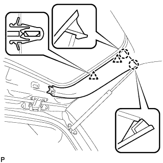
INSTALL BACK WINDOW UPPER TRIM PANEL ASSEMBLY
-
Engage the 4 clips and 4 claws, and install the back window upper trim panel assembly.
-