BACK DOOR DISASSEMBLY
-
PRECAUTION
Note
For the glass hatch type, if any of the following parts are removed and installed or adjusted, the location of the axis of the rear wiper motor assembly will change, causing the wiping angle to change. Be sure to remove and install the rear wiper motor assembly using the centering jig.
Back door glass Rear wiper motor assembly Back door hinge assembly Rear wiper link pivot Back window stay assembly Rear spoiler sub-assembly Back window lock assembly - -
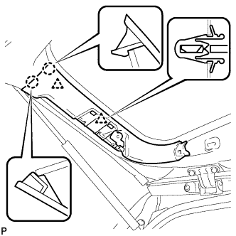
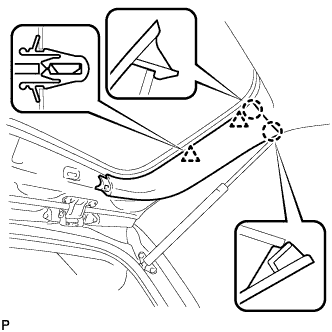
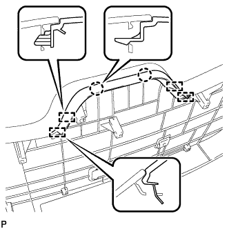
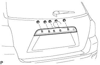
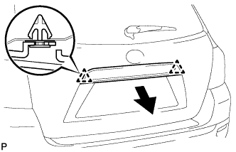
REMOVE BACK WINDOW UPPER TRIM PANEL ASSEMBLY
-
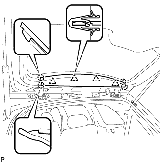
Disengage the 4 clips and 4 claws, and remove the back window upper trim panel assembly.
-
-
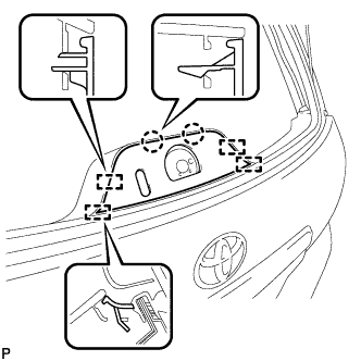
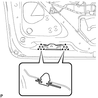
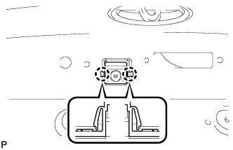
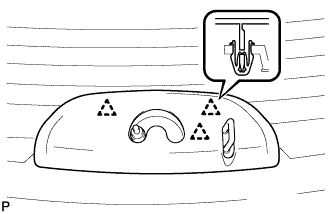
REMOVE BACK DOOR TRIM COVER LH (w/o Power Back Door)
-
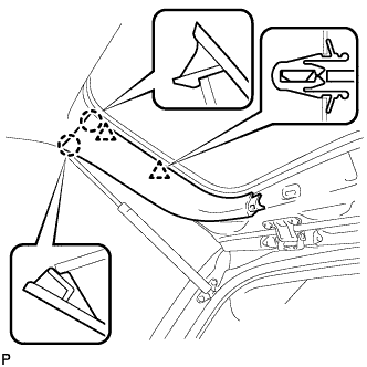
Disengage the 2 clips and 2 claws, and remove the back door trim cover LH.
-
-
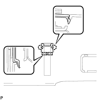
REMOVE BACK DOOR SERVICE HOLE COVER LH (w/ Power Back Door)
-
Disengage the 6 claws, and remove the back door service hole cover LH.
-
-
DISCONNECT POWER BACK DOOR ROD (w/ Power Back Door)
-
Disconnect the power back door rod and remove the back door stay plate.
-
-
REMOVE BACK DOOR TRIM COVER LH (w/ Power Back Door)
-
Disengage the 2 clips and 2 claws, and remove the back door trim cover LH.
-
-
REMOVE BACK DOOR TRIM COVER RH
-
Disengage the 2 clips and 2 claws, and remove the back door trim cover RH.
-
-
REMOVE BACK DOOR LOCK COVER (for Glass Hatch Type)
-
Disengage the 2 claws and 4 guides, and remove the back door lock cover.
-
-
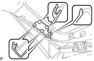
REMOVE ASSIST STRAP HOLE COVER
-
Disengage the 2 claws and 2 guides, and remove the assist strap hole cover.
-
-
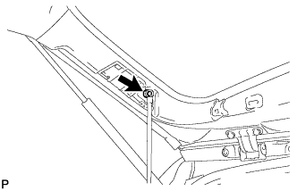
REMOVE ASSIST STRAP ASSEMBLY
-
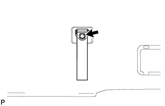
Remove the bolt and assist strap assembly.
-
-
REMOVE BACK DOOR TRIM PANEL ASSEMBLY
-
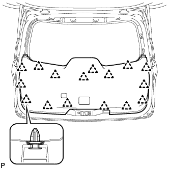
Disengage the 16 clips and remove the back door trim panel assembly.
-
-
REMOVE BACK DOOR LOCK COVER (for Fixed Glass Type)
-
Disengage the 2 claws and 4 guides, and remove the back door lock cover.
-
-
REMOVE BACK PANEL TRIM BRACKET SUB-ASSEMBLY
-
Disengage the 2 clips and remove the back panel trim bracket sub-assembly.
-
-
REMOVE BACK DOOR LOCK ASSEMBLY (w/o Power Back Door)
-
Disconnect the connector.
-
Remove the 3 bolts and back door lock assembly.
-
-
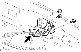
REMOVE BACK DOOR LOCK ASSEMBLY (w/ Power Back Door)
-
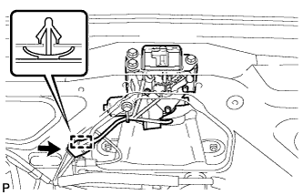
Disconnect the connector.
-
Disengage the clamp.
-
Remove the 4 bolts and back door lock assembly.
-
-
REMOVE POWER BACK DOOR WARNING BUZZER (w/ Power Back Door)
-
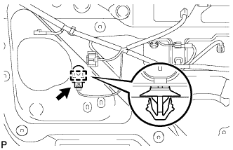
Disconnect the connector.
-
Disengage the clamp and remove the power back door warning buzzer.
-
-
REMOVE POWER BACK DOOR MAIN SWITCH (w/ Power Back Door)
-
Disconnect the connector.
-
Disengage the clamp.
-
Disengage the 4 claws and remove the back door control switch.
-
-
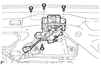
REMOVE POWER BACK DOOR SENSOR ASSEMBLY LH (w/ Power Back Door)
-
Disconnect the connector.
-
Remove the 4 bolts.
-
Disengage the 2 clips and remove the power back door sensor assembly.
-
-
REMOVE POWER BACK DOOR SENSOR ASSEMBLY RH (w/ Power Back Door)
Tech Tips
Use the same procedure for the RH side and the LH side.
-
REMOVE BACK DOOR OUTSIDE GARNISH ASSEMBLY
-
Disconnect each connector.
-
Remove the 5 nuts.
-
Disengage the 2 clips and remove the back door outside garnish assembly.
-
Remove the 2 clips and 5 gaskets.
-
-
REMOVE TELEVISION CAMERA ASSEMBLY (w/ Rear View Monitor System)
-

Disconnect the television camera connector.
-
Disengage the 2 claws and remove the television camera assembly.
-
-
REMOVE REAR WIPER SHAFT COVER (for Glass Hatch Type)
-
Disengage the 3 clips and remove the rear wiper shaft cover.
-
-
REMOVE REAR WIPER ARM HEAD CAP
-
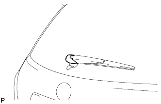
Remove the rear wiper arm head cap.
-
-
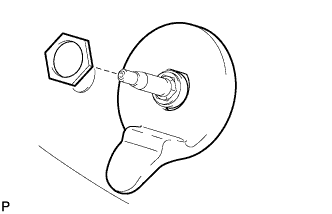
REMOVE REAR WIPER ARM AND BLADE ASSEMBLY
-
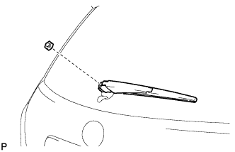
Remove the nut and the rear wiper arm and blade assembly.
-
-
REMOVE REAR WIPER MOTOR GROMMET (for Fixed Glass Type)
-
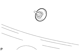
Remove the rear wiper motor grommet.
-
-
REMOVE REAR WIPER LINK CAP (for Glass Hatch Type)
-
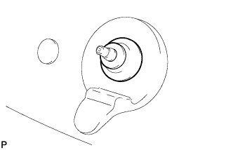
Remove the rear wiper link cap.
-
-
REMOVE REAR WIPER LINK PIVOT (for Glass Hatch Type)
-
Remove the nut and the rear wiper link pivot.
-
-
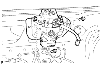
REMOVE REAR WIPER MOTOR ASSEMBLY (for Glass Hatch Type)
-
When reinstalling the rear wiper motor assembly:
-
Open the glass hatch.
-
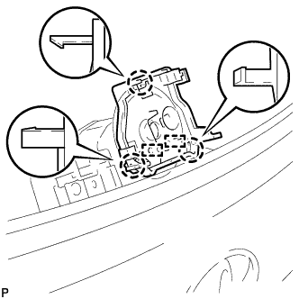
Engage the 3 claws and 2 guides, and then install the centering jig.
Note
-
The centering jig cannot be reused.
-
Do not remove the centering jig before installing the rear wiper link pivot.
-
-
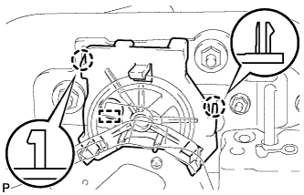
Close the glass hatch, and engage the 2 claws and guide.
Note
Be sure to engage the 2 claws and guide securely.
-
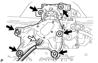
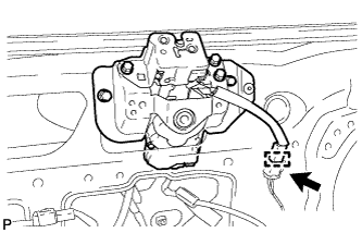
Disconnect the connector.
-
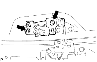
Remove the 2 nuts.
-
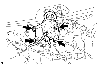
Remove the 4 bolts and the rear wiper motor assembly.
Note
-
Do not hold the rear wiper motor assembly by the rear wiper link pivot.
-
Be careful not to scratch the back door glass.
-
-
-
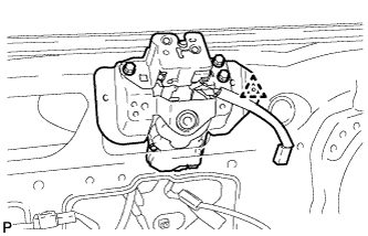
When using a new rear wiper motor assembly:
-
Disconnect the connector.
-
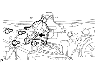
Remove the 4 bolts.
-
Remove the 2 nuts and the rear wiper motor assembly.
Note
Be careful not to scratch the back door glass.
-
-
-
REMOVE REAR WIPER MOTOR ASSEMBLY (for Fixed Glass Type)
-
Disconnect the connector.
-
Remove the 4 bolts and the rear wiper motor assembly.
Note
Be careful not to scratch the back door glass.
-
-
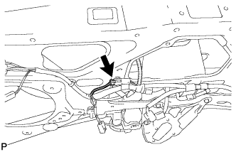
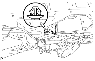
REMOVE BACK WINDOW LOCK ASSEMBLY (for Glass Hatch Type)
-
Disconnect the connector.
-
Disengage the clamp.
-
Remove the 3 bolts.
-
Disengage the clip and remove the back window lock assembly.
-
-
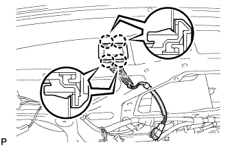
REMOVE BACK DOOR GLASS GUIDE BRACKET SUB-ASSEMBLY (for Fixed Glass Type)
-
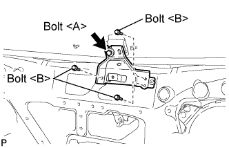
Loosen the bolt <A>.
Note
Bolt <A> cannot be removed from the back door glass guide bracket sub-assembly.
-
Remove the 3 bolts <B>.
-
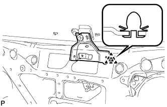
Disengage the clip and remove the back door glass guide bracket sub-assembly.
-
-
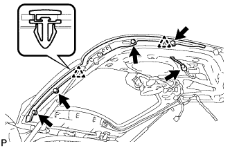
REMOVE REAR SPOILER SUB-ASSEMBLY
-
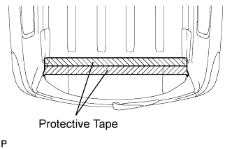
Put protective tape around the rear spoiler sub-assembly.
-
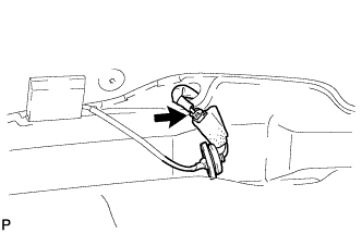
Disconnect the wire harness.
Note
Do not allow the disconnected wire harness to get caught between the back door and the vehicle body to prevent it from being damaged.
-
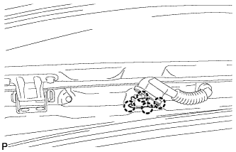
Turn back the wire harness grommet.
-
Disengage the 4 claws and pull out the wire harness from the vehicle.
Note
Do not forcefully pull out the wire harness.
-
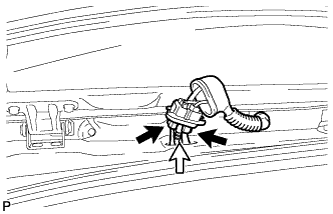
Disconnect the 2 connectors.
-
Disconnect the rear washer hose.
-
Disengage the grommet.
-
Disconnect the connector.
-
-
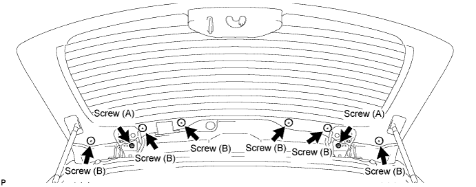
Using a "TORX" socket wrench (T30), remove the 2 screws (A).
-
Using a "TORX" socket wrench (T30), remove the 6 screws (B).
-
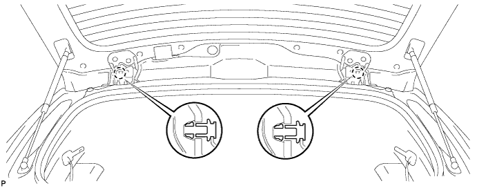
Disengage the 2 claws.
-
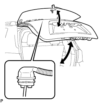
Raise and lower the glass hatch and the back door respectively. Pull out the wire harness from the vehicle and remove the rear spoiler sub-assembly.
-
-
REMOVE BACK WINDOW STAY ASSEMBLY LH (for Glass Hatch Type)
Note
-
Avoid touching the piston rod as much as possible to prevent foreign matter from attaching to it. Be sure to hold the cylinders while servicing.
-
Do not wear cotton gloves or other similar materials when handling the piston rod. Fibers may attach to the piston rod and result in gas leaks.
-
Do not apply any horizontal load to the window stay in the in order to prevent the piston rod from deforming.
-
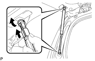
Using a screwdriver with the tip taped, remove the stop ring along the groove.
-
Release the ball joint and remove the back window stay assembly.
Note
Remove the back door stay assembly while supporting the back door by hand.
-
-
REMOVE BACK WINDOW STAY ASSEMBLY RH (for Glass Hatch Type)
Tech Tips
Use the same procedure for the RH side and the LH side.
-
REMOVE BACK DOOR GLASS
-
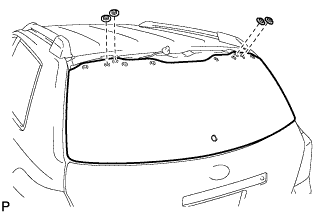
Remove the 4 nuts and back door glass.
-
-
REMOVE NO. 2 BACK DOOR WEATHERSTRIP
-
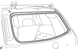
Remove the No. 2 back door weatherstrip.
-