FRONT DOOR DISASSEMBLY
-
DISCONNECT NEGATIVE BATTERY TERMINAL
CAUTION:
Wait for 90 seconds after disconnecting the terminal to prevent airbag deployment Click here.
Note
When disconnecting the cable, some systems need to be initialized after the cable is reconnected Click here.
-
REMOVE FRONT DOOR LOWER FRAME BRACKET GARNISH
-
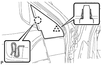
Disengage the claw and clip, and remove the front door lower frame bracket garnish.
-
-
REMOVE FRONT DOOR INSIDE HANDLE BEZEL PLUG
-
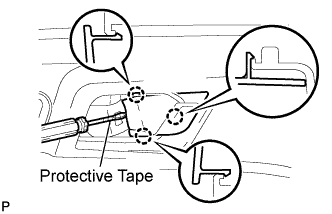
Using a screwdriver with the tip wrapped with protective tape, disengage the 3 claws, and remove the front door inside handle bezel plug.
-
-
REMOVE FRONT ARMREST UPPER BASE PANEL
-
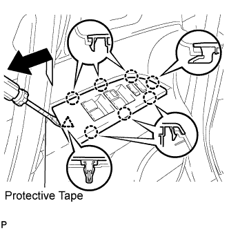
Using a screwdriver with the tip wrapped with protective tape, disengage the 7 claws and clip, and remove the front armrest upper base panel.
-
Disconnect the connector.
-
-
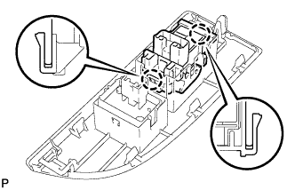
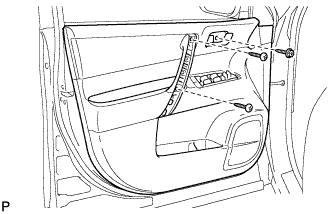
REMOVE POWER WINDOW REGULATOR MASTER SWITCH ASSEMBLY (for Driver Side)
-
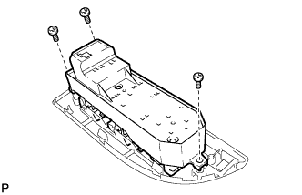
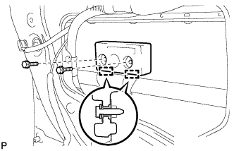
Remove the 3 screws and the power window regulator master switch assembly.
-
-
REMOVE POWER WINDOW REGULATOR SWITCH ASSEMBLY (for Front Passenger Side)
-
Disengage the 2 claws and remove the power window regulator switch assembly.
-
-
REMOVE DOOR CONTROL SWITCH ASSEMBLY (for Front Passenger Side)
-
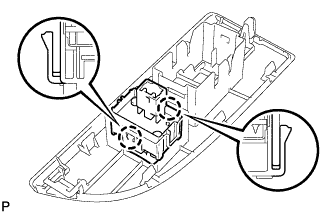
Disengage the 2 claws and remove the door control switch assembly.
-
-
REMOVE ASSIST GRIP COVER
-
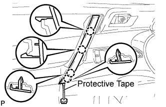
Using a screwdriver with the tip wrapped with protective tape, disengage the 4 claws and remove the assist grip cover.
-
-
REMOVE COURTESY LIGHT ASSEMBLY
-
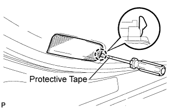
Using a screwdriver with the tip wrapped with protective tape, disengage the claw and remove the courtesy light assembly.
-
Disconnect the connector.
-
-
REMOVE FRONT DOOR TRIM BOARD SUB-ASSEMBLY
-
Remove the 3 screws.
-
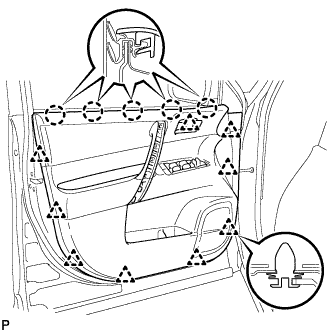
Using a clip remover, disengage the 9 clips.
-
Disengage the 5 claws and separate the front door trim board sub-assembly from the front door inner glass weatherstrip.
-
Disengage the 2 clamps.
-
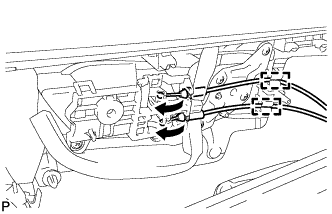
Disconnect the front door lock remote control cable and front door inside locking cable.
-
Disconnect the connector.
-
-
REMOVE FRONT DOOR INSIDE HANDLE SUB-ASSEMBLY
-
Remove the 2 screws.
-
Disengage the 2 claws and remove the front door inside handle sub-assembly.
-
-
REMOVE FRONT DOOR WIRE (for Driver Side)
-
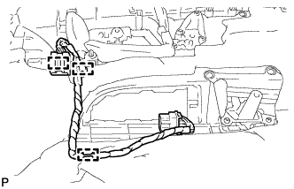
Disengage the 3 clamps and remove the front door wire.
-
-
REMOVE FRONT DOOR INNER GLASS WEATHERSTRIP
-
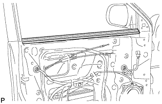
Remove the front door inner glass weatherstrip from the front door panel.
-
-
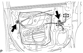
REMOVE FRONT NO. 1 SPEAKER ASSEMBLY
-
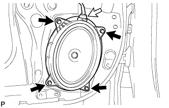
Disconnect the connector.
-
Remove the 4 bolts and front No. 1 speaker assembly.
Note
Do not touch the cone part of the speaker.
-
-
REMOVE OUTER REAR VIEW MIRROR ASSEMBLY WITH COVER
-
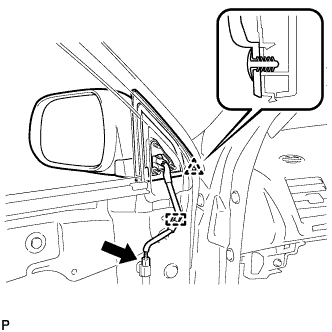
Disconnect the connector and clamp.
-
Disengage the clip.
-
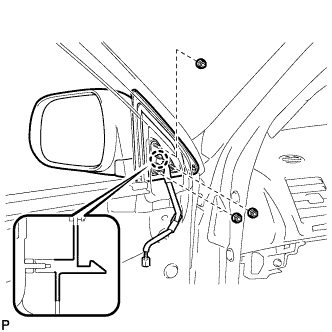
Remove the 3 nuts.
-
Disengage the claw and remove the outer rear view mirror assembly with cover.
-
-
REMOVE FRONT DOOR SERVICE HOLE COVER
-
Disconnect the each connector and 2 clamps, and remove the front door service hole cover.
Tech Tips
Remove the remaining butyl tape on the door side.
-
-
REMOVE FRONT DOOR GLASS SUB-ASSEMBLY
-
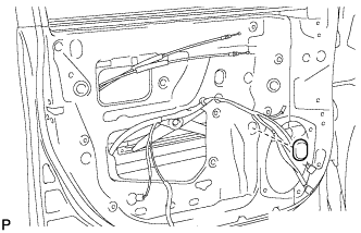
Remove the hole plug.
-
Connect the negative battery terminal.
-
Connect the power window regulator motor connector.
-
Connect the power window regulator master switch assembly and move the front door glass sub-assembly so that the door glass bolts can be seen.
-
Disconnect the negative battery terminal and power window regulator master switch assembly.
-
Disconnect the power window regulator motor connector.
-
Remove the 2 bolts.
Note
After the bolts are removed, do not allow the door to fall.
-
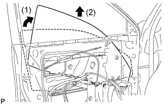
Remove the front door glass sub-assembly as shown in the illustration.
Note
Do not damage the door glass.
-
-
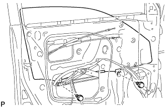
REMOVE FRONT DOOR WINDOW REGULATOR SUB-ASSEMBLY
-
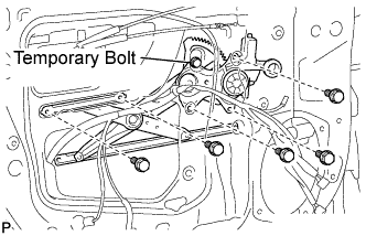
Loosen the temporary bolt.
Note
Do not remove the temporary bolt. If the temporary bolt is removed, the front door window regulator may fall and cause damage.
-
Remove the 5 bolts.
-
Remove the front door window regulator sub-assembly and the front power window regulator motor assembly as a unit.
-
Remove the temporary bolt from the front door window regulator sub-assembly.
-
-
REMOVE FRONT POWER WINDOW REGULATOR MOTOR ASSEMBLY
-
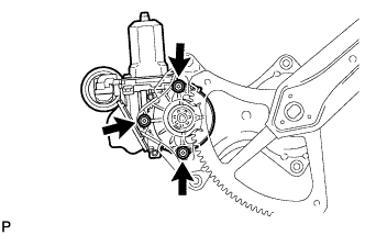
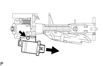
Using a "TORX" driver (T25), remove the 3 screws and the front power window regulator motor assembly.
-
-
REMOVE FRONT DOOR GLASS RUN
-
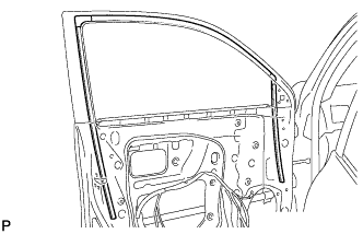
Remove the front door glass run.
-
-
REMOVE FRONT DOOR REAR LOWER FRAME SUB-ASSEMBLY
-
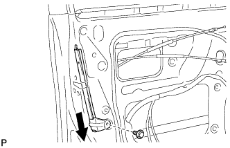
Remove the bolt and the front door rear lower frame sub-assembly as shown in the illustration.
-
-
REMOVE FRONT DOOR OUTSIDE HANDLE COVER (for Driver Side)
-
Remove the hole plug.
-
Using a "TORX" socket wrench (T30), loosen the screw and remove the front door outside handle cover and the door lock key cylinder as a unit.
Tech Tips
The screw cannot be removed because it is integrated into the front door outside handle frame sub-assembly.
-
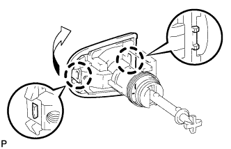
Using a screwdriver, disengage the 2 claws and remove the front door outside handle cover.
-
-
REMOVE FRONT DOOR OUTSIDE HANDLE COVER (for Front Passenger Side)
-
Remove the hole plug.
-
Using a "TORX" socket wrench (T30), loosen the screw and remove the front door outside handle cover and the door lock key cylinder as a unit.
Tech Tips
The screw cannot be removed because it is integrated into the front door outside handle frame sub-assembly.
-
-
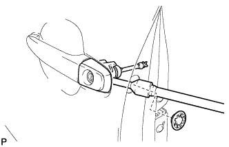
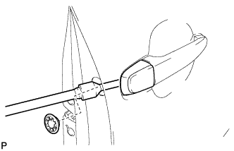
REMOVE FRONT DOOR OUTSIDE HANDLE ASSEMBLY (w/o Smart Entry and Start System)
-
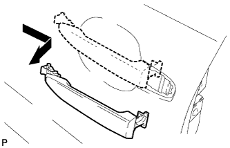
Remove the front door outside handle assembly as shown in the illustration.
-
-
REMOVE FRONT DOOR OUTSIDE HANDLE ASSEMBLY (w/ Smart Entry and Start System)
-
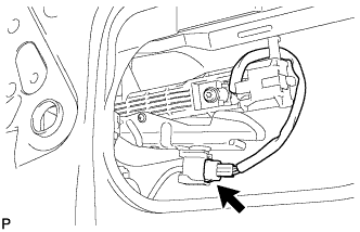
Disconnect the connector.
-
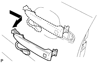
Remove the front door outside handle assembly as shown in the illustration.
-
-
REMOVE FRONT DOOR FRONT OUTSIDE HANDLE PAD
-
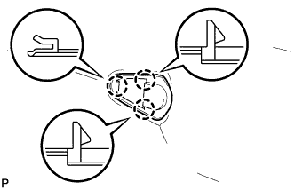
Disengage the 3 claws and remove the front door front outside handle pad.
-
-
REMOVE FRONT DOOR REAR OUTSIDE HANDLE PAD
-
Disengage the 2 claws and remove the front door rear outside handle pad.
-
-
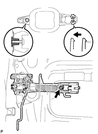
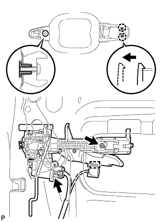
REMOVE FRONT DOOR LOCK ASSEMBLY
-
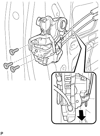
Using a "TORX" socket wrench (T30), remove the 3 screws.
-
Slide the front door lock assembly downward, and remove the front door lock assembly and cables as a unit.
-
Remove the door lock wiring harness seal from the front door lock assembly.
-
-
REMOVE FRONT DOOR LOCK REMOTE CONTROL CABLE ASSEMBLY
-
Remove the front door lock remote control cable assembly.
-
-
REMOVE FRONT DOOR INSIDE LOCKING CABLE ASSEMBLY
-
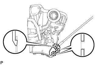
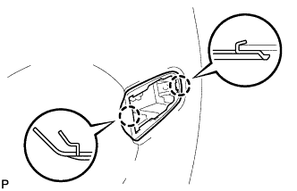
Using a screwdriver, disengage the 3 claws.
Tech Tips
Tape the screwdriver tip before use.
-
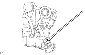
Remove the front door inside locking cable assembly.
-
-
REMOVE FRONT DOOR OUTSIDE HANDLE FRAME SUB-ASSEMBLY (w/o Smart Entry and Start System)
-
Using a "TORX" socket wrench (T30), remove the screw.
-
Disengage the 2 claws and remove the front door outside handle frame sub-assembly.
-
-
REMOVE FRONT DOOR OUTSIDE HANDLE FRAME SUB-ASSEMBLY (w/ Smart Entry and Start System)
-
Using a "TORX" socket wrench (T30), remove the screw.
-
Disconnect the connector.
-
Disengage the clamp.
-
Disengage the 2 claws and remove the front door outside handle frame sub-assembly.
-
-
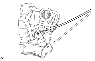
REMOVE FRONT DOOR LOCK OPEN ROD
-
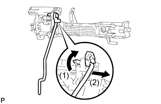
Remove the front door lock open rod as shown in the illustration.
-
-
REMOVE DOOR ELECTRICAL KEY OSCILLATOR (w/ Smart Entry and Start System)
-
Remove the screw and door electrical key oscillator.
-
-
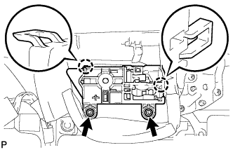
REMOVE FRONT DOOR CHECK ASSEMBLY
-
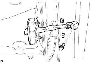
Remove the bolt, 2 nuts, and front door check assembly.
-
-
REMOVE FRONT DOOR WEATHERSTRIP
-
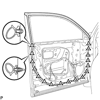
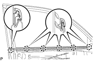
Using a clip remover, disengage the 17 clips and remove the front door weatherstrip.
-
-
REMOVE DOOR FRAME GARNISH
-
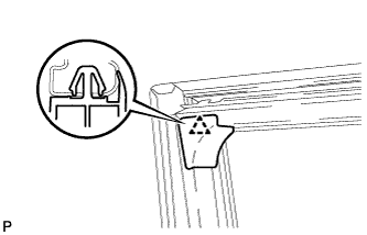
Disengage the clip and remove the door frame garnish.
Tech Tips
This clip needs to be replaced with a new one because the clip will break when removing the door frame garnish.
-
-
REMOVE FRONT DOOR NO. 2 STIFFENER CUSHION
-
Remove the 2 bolts.
-
Remove the 2 guides and the front door No. 2 stiffener cushion.
-
-
REMOVE FRONT DOOR BELT MOULDING ASSEMBLY
-
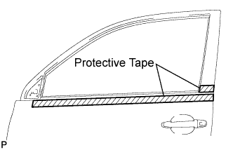
Put protective tape around the front door belt moulding assembly.
-
Disengage the 6 claws and remove the front door belt moulding assembly.
Note
Be careful when removing the moulding as there are claws attached to the front and rear ends of the moulding.
-
-
REMOVE FRONT DOOR WEATHERSTRIP
-
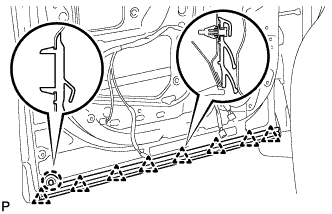
Disengage the claw.
-
Disengage the 8 clips and remove the front door weatherstrip.
-
-
REMOVE FRONT DOOR OUTSIDE MOULDING SUB-ASSEMBLY
-
Turn back the front door weatherstrip.
-
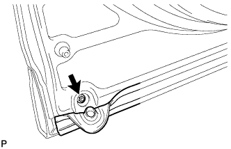
Remove the nut.
-
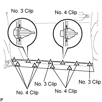
Peel off the upper front door outside moulding pad and disengage the 11 clips, and then remove the front door outside moulding sub-assembly.
-
Remove the gasket from the front door outside moulding sub-assembly.
-
Remove the 3 No. 3 clips pad from the front door outside moulding sub-assembly.
-
Remove the 8 No. 4 clips pad from the front door outside moulding sub-assembly.
-
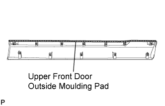
Remove the upper front door outside moulding pad from the front door outside moulding sub-assembly.
-
-
REMOVE NO. 1 BLACK OUT TAPE
-
Using a heat light, heat the No. 1 black out tape and vehicle body.
Heating temperature Item Temperature Vehicle Body 40 to 60°C (104 to 140°F) Note
Do not heat the vehicle body excessively.
-
Pull back an end of the No. 1 black out tape and pull it parallel to the vehicle body to pull it off.
-
-
REMOVE INNER UPPER BLACK OUT FRONT DOOR TAPE
-
Using a heat light, heat the inner upper black out front door tape and vehicle body.
Heating temperature Item Temperature Vehicle Body 40 to 60°C (104 to 140°F) Note
Do not heat the vehicle body excessively.
-
Pull back an end of the inner upper black out front door tape and pull it parallel to the vehicle body to pull it off.
-
-
REMOVE INNER REAR BLACK OUT FRONT DOOR TAPE
-
Using a heat light, heat the inner rear black out front door tape and vehicle body.
Heating temperature Item Temperature Vehicle Body 40 to 60°C (104 to 140°F) Note
Do not heat the vehicle body excessively.
-
Pull back an end of the inner rear black out front door tape and pull it parallel to the vehicle body to pull it off.
-