HOOD LOCK CONTROL CABLE ASSEMBLY INSTALLATION
-
INSTALL HOOD LOCK CONTROL CABLE ASSEMBLY
-
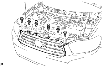
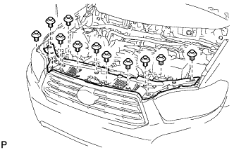
Pass the hood lock control cable assembly into the engine compartment.
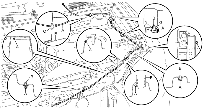
Area Part Name Area Part Name A Hood lock control cable E Fender liner B Clamp F Hood stopper rubber C Hood cable grommet G Front washer hose D Wire harness H Rear washer hose -
Pass the cable through the upper radiator support.
-
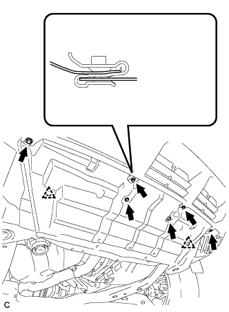
Connect the clamps as shown in the illustration.
-
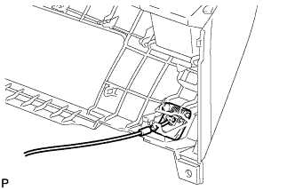
Connect the hood lock control cable to the hood lock control lever.
-
-
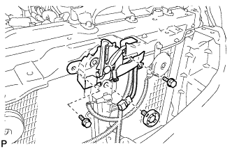
INSTALL HOOD LOCK ASSEMBLY (w/o Engine Hood Courtesy Switch)
-
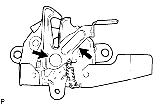
Apply MP grease to the sliding areas of the lock.
-
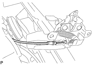
Connect the hood lock control cable.
-
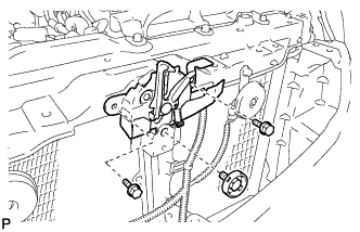
Install the hood lock assembly with the 3 bolts.
- Torque:
- 8.0 N*m { 82 kgf*cm, 71 in.*lbf }
-
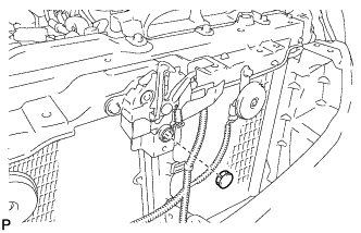
Install the hood lock nut cap.
-
-
INSTALL HOOD LOCK ASSEMBLY (w/ Engine Hood Courtesy Switch)
-
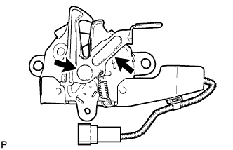
Apply MP grease to the sliding areas of the lock.
-
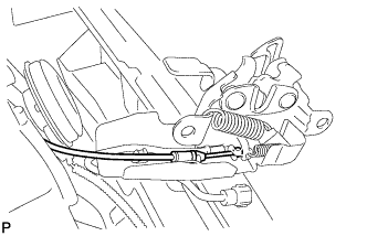
Connect the hood lock control cable.
-
Install the hood lock assembly with the 3 bolts.
- Torque:
- 8.0 N*m { 82 kgf*cm, 71 in.*lbf }
-
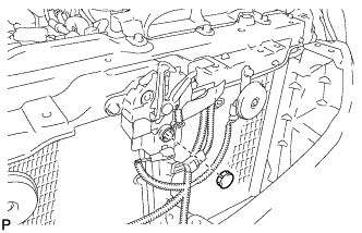
Install the hood lock nut cap.
-
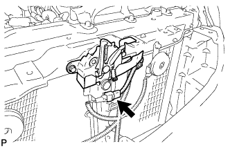
Connect the connector.
-
-
INSPECT HOOD SUB-ASSEMBLY
-
Check that the clearance measurements of areas A through D are within each standard range.
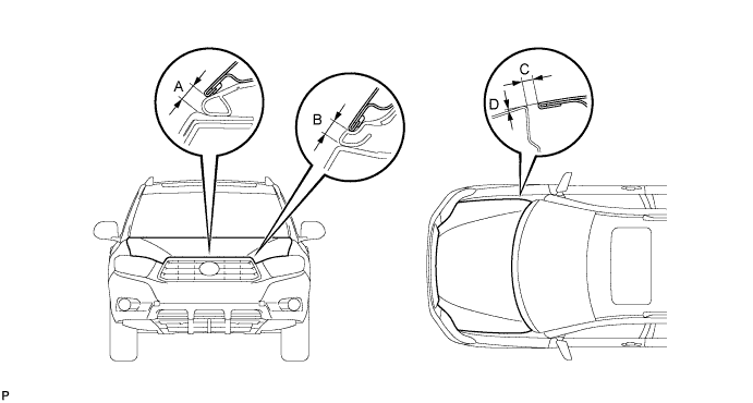
Standard clearance Area Measurement Area Measurement A 6.2 to 10.2 mm (0.244 to 0.402 in.) C 2.5 to 5.5 mm (0.098 to 0.217 in.) B 5.9 to 9.9 mm (0.232 to 0.390 in.) D -1.5 to 1.5 mm (-0.059 to 0.059 in.)
-
-
ADJUST HOOD SUB-ASSEMBLY
-
Horizontally and vertically adjust the hood.
-
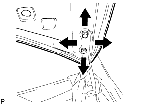
Loosen the 4 hinge bolts of the hood.
-
Adjust the clearance between the hood and front fender by moving the hood.
-
Tighten the 4 hinge bolts after the adjustment.
- Torque:
- 13 N*m { 133 kgf*cm, 10 ft.*lbf }
-
-
Adjust the height of the front end of the hood using the cushion rubber.
-
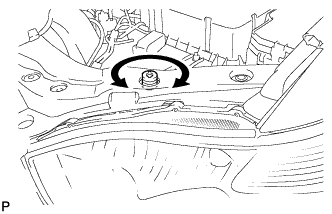
Adjust the cushion rubbers so that the heights of the hood and fender are aligned.
Tech Tips
Raise or lower the front end of the hood by turning the cushion rubber.
-
-
Adjust the hood lock.
-
Remove the hood lock nut cap.
-
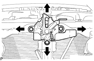
Loosen the 3 bolts.
-
Tighten the bolts after the adjustment.
- Torque:
- 8.0 N*m { 82 kgf*cm, 71 in.*lbf }
-
Install the hood lock nut cap.
-
Check that the striker can engage with the hood lock smoothly.
-
-
-
INSTALL RADIATOR GRILLE
-
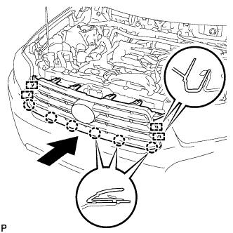
Engage the 4 guides and 6 claws, and install the radiator grille.
-
Install the 4 clips and 2 bolts.
-
-
INSTALL COOL AIR INTAKE DUCT SEAL
-
Install the cool air intake duct seal with the 11 clips.
-
-
INSTALL FRONT FENDER LINER LH
-
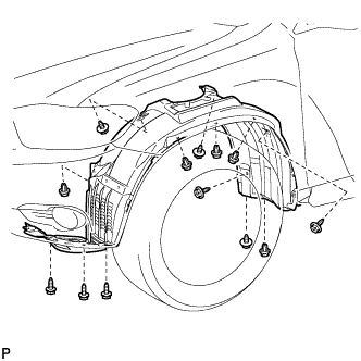
Install the front fender liner LH with the 5 clips and 8 screws.
-
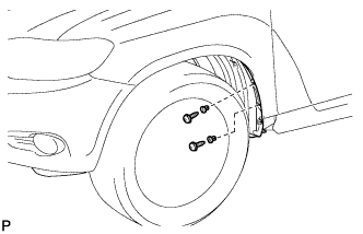
Install 2 new grommets.
-
Using a 4 mm hexagon wrench, install the 2 screws.
-
Install the screw and pin hold clip.
- Torque:
- 3.0 N*m { 31 kgf*cm, 27 in.*lbf }
-
-
INSTALL FRONT FENDER MOULDING SUB-ASSEMBLY LH
-
Clean the vehicle body surface.
-
Using a heat light, heat the vehicle body surface.
-
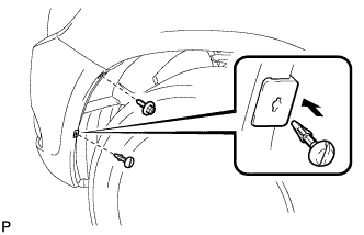
Remove the front fender side protector from the vehicle body.
-
Wipe off any tape adhesive residue with cleaner.
-
-
Clean the front fender moulding sub-assembly. (If reusing the front fender moulding sub-assembly)
-
Using a heat light, heat the front fender moulding sub-assembly.
-
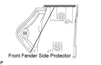
Remove the front fender side protector from the front fender moulding sub-assembly.
-
Wipe off any tape adhesive residue with cleaner.
-
Install a new front fender side protector to the the front fender moulding sub-assembly.
-
-
Install 2 new No. 4 clips on the front fender moulding sub-assembly.
-
Install a new pad on the front fender moulding sub-assembly.
-
Install the front fender moulding sub-assembly.
-
Using a heat light, heat the vehicle body and the front fender moulding sub-assembly.
-
Remove the release paper from the front fender moulding sub-assembly.
Tech Tips
After removing the release paper, keep the exposed adhesive free from foreign matter.
-
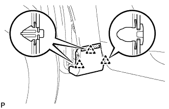
Engage the 3 clips and install the front fender moulding sub-assembly.
-
-
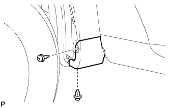
Using a 4 mm hexagon wrench, install the screw.
-
Install the clip.
-
-
INSTALL NO. 1 ENGINE UNDER COVER
-
Install the No. 1 engine under cover with the 6 bolts and 2 clips.
-
-
INSTALL ENGINE UNDER COVER ASSEMBLY
-

Install the engine under cover assembly with the 2 bolts, 2 screws and 5 clips.
-

Install the engine under cover assembly RR with the 2 bolts.
-