BACK DOOR CLOSER SYSTEM Back Door cannot be Opened
DESCRIPTION
When the back door cannot be opened, one of the following may be malfunctioning: 1) power back door drive unit (power back door ECU), or 2) back door lock, or 3) back door open switch, or 4) main body ECU (instrument panel junction block).
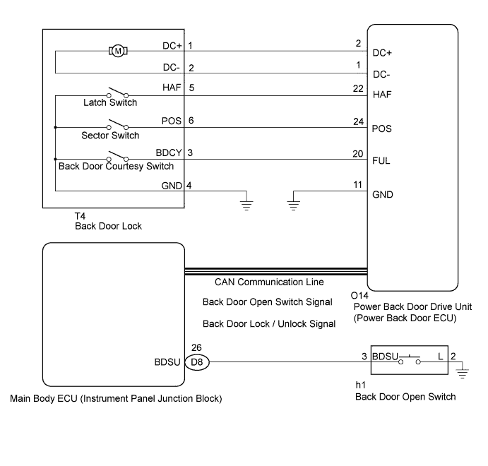
WIRING DIAGRAM
INSPECTION PROCEDURE
PROCEDURE
-
READ VALUE ON INTELLIGENT TESTER
-
Check the Data List to determine if the back door lock function properly.
Back Door (Power back door ECU) Tester Display Measurement Item/Range Normal Condition Diagnostic Note Door Lock Status Back door lock condition signal / LOCK or UNLOCK LOCK: Back door is locked
UNLOCK: Back door is unlocked
- OK The back door functions as specified in the normal condition.
NG 
REPLACE POWER BACK DOOR DRIVE UNIT (POWER BACK DOOR ECU) Click here
OK 
-
-
READ VALUE ON INTELLIGENT TESTER
-
Check the Data List to determine if the back door handle switch function properly.
Main body ECU (Instrument panel junction block) Tester Display Measurement Item/Range Normal Condition Diagnostic Note Back Door Open Handle SW Back door opener switch / ON or OFF ON: Back door opener switch is pushed
OFF: Back door opener switch is not pushed
- OK The back door opener switch functions as specified in the normal condition.
NG
INSPECT BACK DOOR OPENER SWITCH Click here
OK
-
-
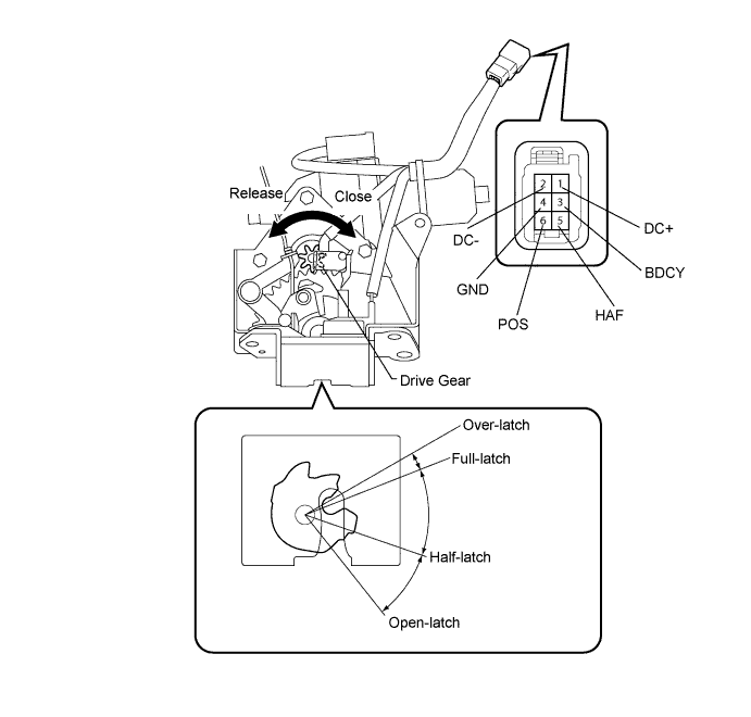
INSPECT BACK DOOR LOCK
-
Remove the back door lock Click here.
-
Apply battery voltage and check operation of the door lock motor.
OK Measurement Condition Specified Condition Battery positive (+) → Terminal 1 (DC+)
Battery negative (-) → Terminal 2 (DC-)
Latch turns to full-latch position Battery positive (+) → Terminal 2 (DC-)
Battery negative (-) → Terminal 1 (DC+)
Latch turns to open-latch position -
Measure the resistance of the switch.
Standard resistance Full-latch switch Tester Connection Door Lock Latch Position Specified Condition 5 (HAF) - 4 (GND) Over-latch Below 1 Ω 5 (HAF) - 4 (GND) Open-latch 10 kΩ or higher 5 (HAF) - 4 (GND) Full-latch 10 kΩ or higher 5 (HAF) - 4 (GND) Half-latch 10 kΩ or higher Sector switch Tester Connection Door Lock Latch Position Specified Condition 6 (POS) - 4 (GND) Open-latch Below 1 Ω 6 (POS) - 4 (GND) Over-latch 10 kΩ or higher 6 (POS) - 4 (GND) Full-latch 10 kΩ or higher 6 (POS) - 4 (GND) Half-latch 10 kΩ or higher Back door courtesy light switch Tester Connection Door Lock Latch Position Specified Condition 3 (BDCY) - 4 (GND) Open-latch Below 1 Ω 3 (BDCY) - 4 (GND) Half-latch Below 1 Ω 3 (BDCY) - 4 (GND) Full-latch 10 kΩ or higher 3 (BDCY) - 4 (GND) Over-latch 10 kΩ or higher
NG 
REPLACE BACK DOOR LOCK Click here
OK
-
-
CHECK HARNESS AND CONNECTOR (BACK DOOR LOCK - POWER BACK DOOR ECU)
-
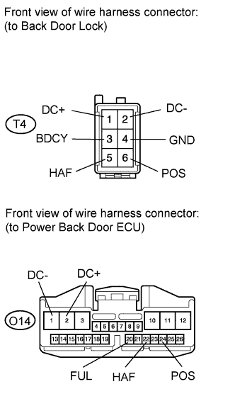
Disconnect the T4 back door lock connector.
-
Disconnect the O14 ECU connector.
-
Measure the resistance according to the value(s) in the table below.
Standard resistance Tester Connection Condition Specified Condition T4-1 (DC+) - O14-2 (DC+) Always Below 1 Ω T4-2 (DC-) - O14-1 (DC-) Always Below 1 Ω T4-5 (HAF) - O14-22 (HAF) Always Below 1 Ω T4-6 (POS) - O14-24 (POS) Always Below 1 Ω T4-3 (BDCY) - O14-20 (FUL) Always Below 1 Ω T4-4 (GND) - Body ground Always Below 1 Ω T4-1 (DC+) - Body ground Always 10 kΩ or higher T4-2 (DC-) - Body ground Always 10 kΩ or higher T4-5 (HAF) - Body ground Always 10 kΩ or higher T4-6 (POS) - Body ground Always 10 kΩ or higher T4-3 (BDCY) - Body ground Always 10 kΩ or higher
NG
REPAIR OR REPLACE HARNESS OR CONNECTOR
OK 
REPLACE POWER BACK DOOR DRIVE UNIT (POWER BACK DOOR ECU) Click here
-
-
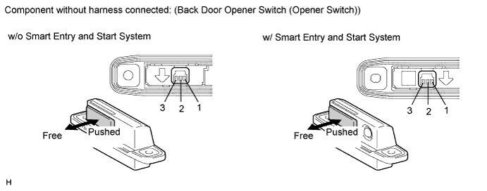
INSPECT BACK DOOR OPENER SWITCH
-
Remove the back door opener switch Click here.
-
Measure the resistance according to the value(s) in the table below.
Standard resistance Tester Connection Switch Position Specified Condition 2 - 3 Back door opener switch not pushed (OFF) 10 kΩ or higher 2 - 3 Back door opener switch pushed (ON) Below 1 Ω
NG
REPLACE BACK DOOR OPENER SWITCH Click here
OK
-
-
CHECK HARNESS AND CONNECTOR (BACK DOOR OPENER SWITCH - MAIN BODY ECU)
-
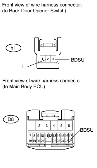
Disconnect the h1 switch connection.
-
Disconnect the D8 ECU connector.
-
Measure the resistance according to the value(s) in the table below.
Standard resistance Tester Connection Condition Specified Condition h1-3 (BDSU) - D8-26 (BDSU) Always Below 1 Ω h1-2 (L) - Body ground Always Below 1 Ω h1-3 (BDSU) - Body ground Always 10 kΩ or higher
NG
REPAIR OR REPLACE HARNESS OR CONNECTOR
OK
REPLACE MAIN BODY ECU (INSTRUMENT PANEL JUNCTION BLOCK)
-
-
REPLACE POWER BACK DOOR DRIVE UNIT (POWER BACK DOOR ECU)
-
Replace the power back door drive unit (power back door ECU) Click here.
NEXT
-
-
CHECK POWER BACK DOOR DRIVE UNIT (POWER BACK DOOR ECU)
-
Check that the back door closer operates normally.
OK It operates normally.
NG
REPLACE MAIN BODY ECU (INSTRUMENT PANEL JUNCTION BLOCK)
OK
END (REPLACE POWER BACK DOOR DRIVE UNIT (POWER BACK DOOR ECU) DEFECTIVE)
-