BACK DOOR CLOSER SYSTEM Back Door Closer does not Operate
DESCRIPTION
When the back door closer does not operate, one of the following may be the cause 1) improper fit of back door, or a foreign object is stuck in back door, or 2) initialization of the power back door ECU, or a malfunction in the 3) power back door ECU power source circuit, or 4) back door lock circuit, or 5) power back door ECU.
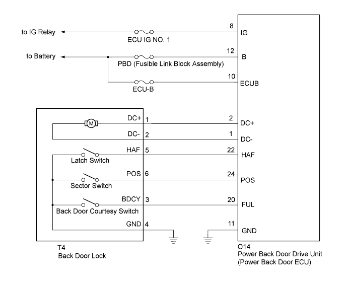
WIRING DIAGRAM
INSPECTION PROCEDURE
PROCEDURE
-
CHECK BACK DOOR LOCK FUNCTION
-
Check if the back door is fully closed by hand.
NG 
IMPROPER FIT OF BACK DOOR, OR A FOREIGN OBJECT IS STUCK IN BACK DOOR
OK 
-
-
INITIALIZE POWER BACK DOOR ECU
-
Check that the power back door drive unit (power back door ECU) can be initialized Click here.
NEXT
-
-
CHECK BACK DOOR CLOSER SYSTEM
-
Check that the back door closer system operation.
OK Back door closer system operates normally.
NG 
CHECK DTC OUTPUT Click here
OK 
END
-
-
CHECK DTC OUTPUT
-
Check for the DTCs Click here.
Result Result Proceed to DTC is not output A B2250 is output B B2251 is output C
B
GO TO DTC CHART (B2250) Click here
C
GO TO DTC CHART (B2251) Click here
A
-
-
INSPECT FUSE (ECU IG NO. 1, ECU-B)
-
Remove the ECU IG No. 1 fuse from the instrument panel junction block and ECU-B fuse from the engine room relay block.
-
Measure the resistance according to the value(s) in the table below.
Standard resistance Tester Connection Condition Specified Condition ECU IG NO. 1 Always Below 1 Ω ECU-B Always Below 1 Ω
NG
REPLACE FUSE
OK
-
-
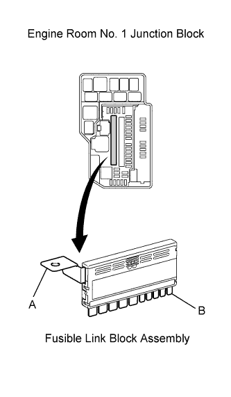
CHECK FUSIBLE LINK BLOCK ASSEMBLY (PBD FUSE)
-
Remove the fusible link block assembly.
-
Measure the resistance according to the value(s) in the table below.
Standard resistance Tester Connection Condition Specified Condition A - B Always Below 1 Ω Tech Tips
PBD 30A fuse is located in the fusible link block assembly.
NG
REPLACE FUSIBLE LINK BLOCK ASSEMBLY
OK
-
-
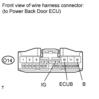
CHECK HARNESS AND CONNECTOR (BODY GROUND)
-
Disconnect the O14 power back door ECU connector.
-
Measure the voltage according to the value(s) in the table below.
Standard voltage Tester Connection Condition Specified Condition O14-8 (IG) - Body ground Ignition switch on (IG) 11 to 14 V O14-10 (ECUB) - Body ground Always 11 to 14 V O14-12 (B) - Body ground Always 11 to 14 V
NG
REPAIR OR REPLACE HARNESS OR CONNECTOR
OK
-
-
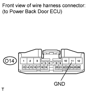
CHECK HARNESS AND CONNECTOR (POWER SOURCE)
-
Disconnect the O14 power back door ECU connector.
-
Measure the resistance according to the value(s) in the table below.
Standard resistance Tester Connection Condition Specified Condition O14-11 (GND) - Body ground Always Below 1 Ω
NG
REPAIR OR REPLACE HARNESS OR CONNECTOR
OK
-
-
INSPECT BACK DOOR LOCK
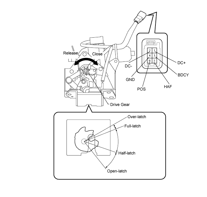
-
Remove the back door lock. Click here
-
Apply battery voltage and check operation of the door lock motor.
OK Measurement Condition Specified Condition Battery positive (+) → Terminal 1 (DC+)
Battery negative (-) → Terminal 2 (DC-)
Latch turns to full-latch position Battery positive (+) → Terminal 2 (DC-)
Battery negative (-) → Terminal 1 (DC+)
Latch turns to open-latch position -
Measure the resistance of the switch.
Standard resistance Full-latch switch Tester Connection Door Lock Latch Position Specified Condition 5 (HAF) - 4 (GND) Over-latch Below 1 Ω 5 (HAF) - 4 (GND) Open-latch 10 kΩ or higher 5 (HAF) - 4 (GND) Full-latch 10 kΩ or higher 5 (HAF) - 4 (GND) Half-latch 10 kΩ or higher Back door courtesy light switch Tester Connection Door Lock Latch Position Specified Condition 3 (BDCY) - 4 (GND) Open-latch Below 1 Ω 3 (BDCY) - 4 (GND) Half-latch Below 1 Ω 3 (BDCY) - 4 (GND) Full-latch 10 kΩ or higher 3 (BDCY) - 4 (GND) Over-latch 10 kΩ or higher
NG
REPLACE BACK DOOR LOCK Click here
OK
-
-
CHECK HARNESS AND CONNECTOR (BACK DOOR LOCK - POWER BACK DOOR ECU AND BODY GROUND)
-
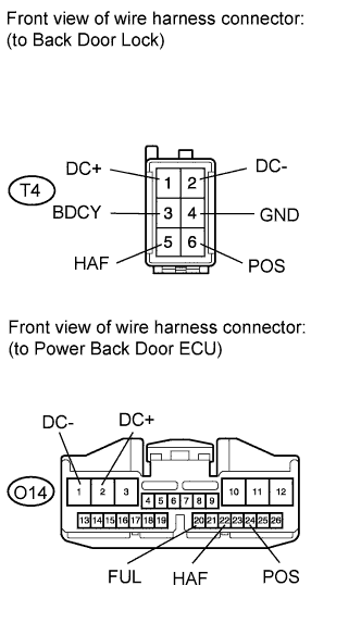
Disconnect the T4 door lock connector.
-
Disconnect the O14 ECU connector.
-
Measure the resistance according to the value(s) in the table below.
Standard resistance Tester Connection Condition Specified Condition T4-1 (DC+) - O14-2 (DC+) Always Below 1 Ω T4-2 (DC-) - O14-1 (DC-) Always Below 1 Ω T4-5 (HAF) - O14-22 (HAF) Always Below 1 Ω T4-6 (POS) - O14-24 (POS) Always Below 1 Ω T4-3 (BDCY) - O14-20 (FUL) Always Below 1 Ω T4-4 (GND) - Body ground Always Below 1 Ω T4-1 (DC+) - Body ground Always 10 kΩ or higher T4-2 (DC-) - Body ground Always 10 kΩ or higher T4-5 (HAF) - Body ground Always 10 kΩ or higher T4-6 (POS) - Body ground Always 10 kΩ or higher T4-3 (BDCY) - Body ground Always 10 kΩ or higher
NG
REPAIR OR REPLACE HARNESS OR CONNECTOR
OK
REPLACE POWER BACK DOOR DRIVE UNIT (POWER BACK DOOR ECU)
-