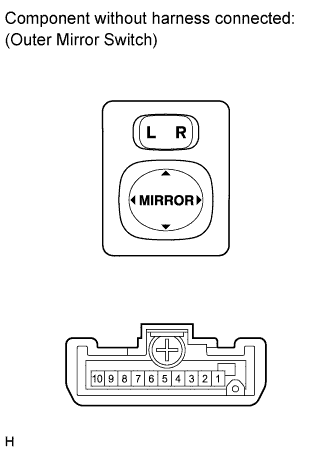
OUTER MIRROR SWITCH INSPECTION
-
INSPECT OUTER MIRROR SWITCH ASSEMBLY
-
The L position of the left/right adjustment switch: Measure the resistance according to the value(s) in the table below.
Standard resistance (for left side) Tester Connection Switch Condition Specified Condition 4 (MLV) - 8 (B)
6 (M+) - 7 (E)
UP Below 1 Ω OFF 10 kΩ or higher 4 (MLV) - 7 (E)
6 (M+) - 8 (B)
DOWN Below 1 Ω OFF 10 kΩ or higher 5 (MLH) - 8 (B)
6 (M+) - 7 (E)
LEFT Below 1 Ω OFF 10 kΩ or higher 5 (MLH) - 7 (E)
6 (M+) - 8 (B)
RIGHT Below 1 Ω OFF 10 kΩ or higher If the result is not as specified, replace the switch assembly.
-
The R position of the left/right adjustment switch: Measure the resistance according to the value(s) in the table below.
Standard resistance (for right side) Tester Connection Switch Condition Specified Condition 3 (MRV) - 8 (B)
6 (M+) - 7 (E)
UP Below 1 Ω OFF 10 kΩ or higher 3 (MRV) - 7 (E)
6 (M+) - 8 (B)
DOWN Below 1 Ω OFF 10 kΩ or higher 2 (MRH) - 8 (B)
6 (M+) - 7 (E)
LEFT Below 1 Ω OFF 10 kΩ or higher 2 (MRH) - 7 (E)
6 (M+) - 8 (B)
RIGHT Below 1 Ω OFF 10 kΩ or higher If the result is not as specified, replace the switch assembly.
-