- Click here
INSPECT OUTER REAR VIEW MIRROR ASSEMBLY RH
-
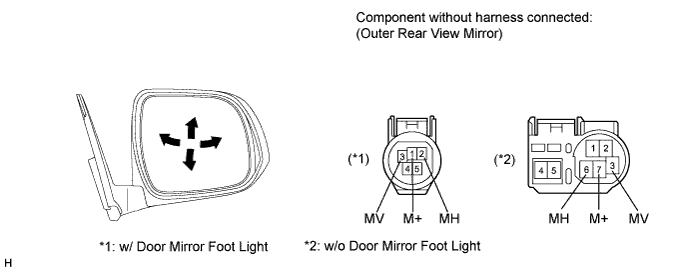
Disconnect the mirror connector.
-
Apply battery voltage and check the operation of the mirror.
OK w/ Door Mirror Foot Light Measurement Condition Specified Condition Battery positive (+) → Terminal 3 (MV)
Battery negative (-) → Terminal 1 (M+)
Turns upward Battery positive (+) → Terminal 1 (M+)
Battery negative (-) → Terminal 3 (MV)
Turns downward Battery positive (+) → Terminal 2 (MH)
Battery negative (-) → Terminal 1 (M+)
Turns left Battery positive (+) → Terminal 1 (M+)
Battery negative (-) → Terminal 2 (MH)
Turns right w/o Door Mirror Foot Light Measurement Condition Specified Condition Battery positive (+) → Terminal 3 (MV)
Battery negative (-) → Terminal 7 (M+)
Turns upward Battery positive (+) → Terminal 7 (M+)
Battery negative (-) → Terminal 3 (MV)
Turns downward Battery positive (+) → Terminal 6 (MH)
Battery negative (-) → Terminal 7 (M+)
Turns left Battery positive (+) → Terminal 7 (M+)
Battery negative (-) → Terminal 6 (MH)
Turns right If the result is not as specified, replace the mirror assembly.
-
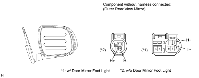
w/ Mirror Heater:
Check the resistance.
-
Measure the resistance according to the value(s) in the table bellow.
Standard resistance w/ Door Mirror Foot Light Tester Connection Condition Specified Condition 2 (H+) - 1 (H-) Always 3.8 to 4.8 Ω w/o Door Mirror Foot Light Tester Connection Condition Specified Condition 4 (H+) - 5 (H-) Always 3.8 to 4.8 Ω If the result is not as specified, replace the outer rear view mirror.
-
Connect the cable from the positive battery (+) terminal to terminal 2*1 or 4*2 and the negative battery (-) terminal to terminal 1*1 or 5*2, then check that the mirror becomes warm.
Tip:
-
*1: w/ Door Mirror Foot Light
-
*2: w/o Door Mirror Foot Light
OK Mirror becomes warm. Tip:It takes a short time for the mirror to become warm.
If the result is not as specified, replace the outer rear view mirror.
-
-
-
- Click here
INSPECT OUTER REAR VIEW MIRROR ASSEMBLY LH
-
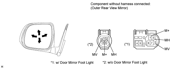
Disconnect the mirror connector.
-
Apply battery voltage and check the operation of the mirror.
OK w/ Door Mirror Foot Light Measurement Condition Specified Condition Battery positive (+) → Terminal 3 (MV)
Battery negative (-) → Terminal 1 (M+)
Turns upward Battery positive (+) → Terminal 1 (M+)
Battery negative (-) → Terminal 3 (MV)
Turns downward Battery positive (+) → Terminal 2 (MH)
Battery negative (-) → Terminal 1 (M+)
Turns left Battery positive (+) → Terminal 1 (M+)
Battery negative (-) → Terminal 2 (MH)
Turns right w/o Door Mirror Foot Light Measurement Condition Specified Condition Battery positive (+) → Terminal 3 (MV)
Battery negative (-) → Terminal 7 (M+)
Turns upward Battery positive (+) → Terminal 7 (M+)
Battery negative (-) → Terminal 3 (MV)
Turns downward Battery positive (+) → Terminal 6 (MH)
Battery negative (-) → Terminal 7 (M+)
Turns left Battery positive (+) → Terminal 7 (M+)
Battery negative (-) → Terminal 6 (MH)
Turns right If the result is not as specified, replace the mirror assembly.
-
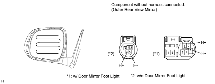
w/ Mirror Heater:
Check the resistance.
-
Measure the resistance according to the value(s) in the table bellow.
Standard resistance w/ Door Mirror Foot Light Tester Connection Condition Specified Condition 2 (H+) - 1 (H-) Always 3.8 to 4.8 Ω w/o Door Mirror Foot Light Tester Connection Condition Specified Condition 4 (H+) - 5 (H-) Always 3.8 to 4.8 Ω If the result is not as specified, replace the outer rear view mirror.
-
Connect the cable from the positive battery (+) terminal to terminal 2*1 or 4*2 and the negative battery (-) terminal to terminal 1*1 or 5*2, then check that the mirror becomes warm.
Tip:
-
*1: w/ Door Mirror Foot Light
-
*2: w/o Door Mirror Foot Light
OK Mirror becomes warm. Tip:It takes a short time for the mirror to become warm.
If the result is not as specified, replace the outer rear view mirror.
-
-
-