- Click here
PRECAUTION
- Click here
POSITION FRONT WHEELS STRAIGHT AHEAD
- Click here
DISCONNECT CABLE FROM NEGATIVE BATTERY TERMINAL
CAUTION:Wait for 90 seconds after disconnecting the terminal to prevent airbag deployment (Click here).
Note:When disconnecting the cable, some systems need to be initialized after the cable is reconnected (Click here).
- Click here
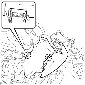
REMOVE LOWER NO. 3 STEERING WHEEL COVER
-
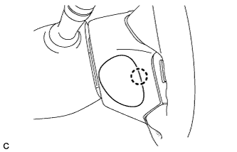
Disengage the claw and remove the lower No. 3 steering wheel cover.
-
- Click here
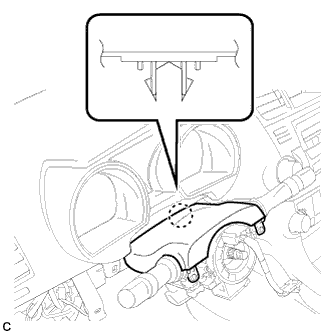
REMOVE LOWER NO. 2 STEERING WHEEL COVER
-
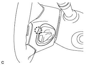
Disengage the claw and remove the lower No. 2 steering wheel cover.
-
- Click here
REMOVE STEERING PAD
-
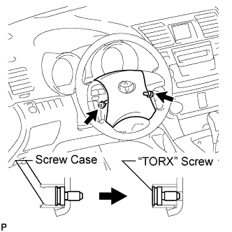
Using a "TORX" socket wrench (T30), loosen the 2 "TORX" screws until the groove along the screw circumference catches on the screw case.
-
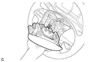
Pull out the steering pad from the steering wheel assembly and support the steering pad with one hand as shown in the illustration.
Note:When removing the steering pad, do not pull the airbag wire harness.
-
Disconnect the horn connector from the steering pad.
-
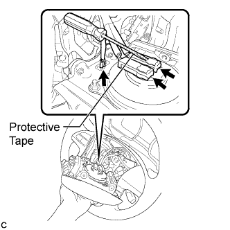
Using a screwdriver with the tip wrapped with protective tape, disconnect the 2 airbag connectors and remove the steering pad.
Note:When handling the airbag connector, take care not to damage the airbag wire harness.
-
- Click here
REMOVE STEERING WHEEL ASSEMBLY
-
Remove the steering wheel assembly set nut.
-
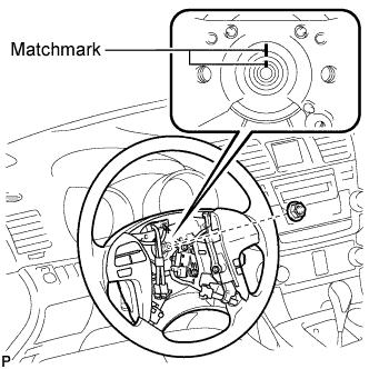
Put matchmarks on the steering wheel assembly and the steering main shaft.
-
Disconnect the connectors from the spiral cable.
-
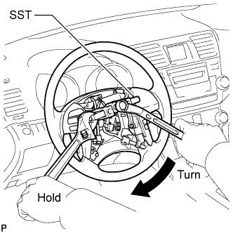
Using SST, remove the steering wheel assembly.
09950-50013 09951-05010 09952-05010 09953-05020 09954-05021 Note:Apply a small amount of grease to the threads and tip of SST (09953-05020) before use.
-
- Click here
REMOVE STEERING COLUMN COVER
-
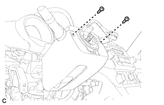
Remove the 2 screws.
-
Disengage the 2 claws to remove the lower steering column cover.
-
Disengage the claw to remove the upper steering column cover.
-
- Click here
REMOVE TURN SIGNAL SWITCH ASSEMBLY WITH SPIRAL CABLE SUB-ASSEMBLY
-
Disconnect the connectors from the turn signal switch assembly with spiral cable sub-assembly.
-
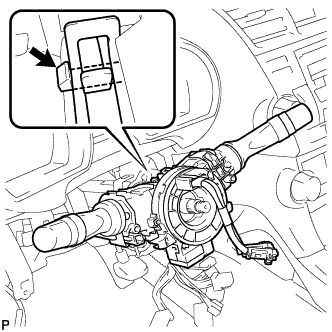
Using pliers, grip the claws of the clip and remove the turn signal switch assembly with spiral cable sub-assembly.
-
- Click here
REMOVE INSTRUMENT CLUSTER FINISH PANEL ASSEMBLY
-
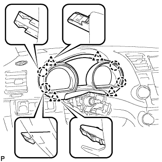
Disengage the 4 claws and 4 clips, and remove the instrument cluster finish panel assembly.
-
- Click here
REMOVE COMBINATION METER ASSEMBLY
-
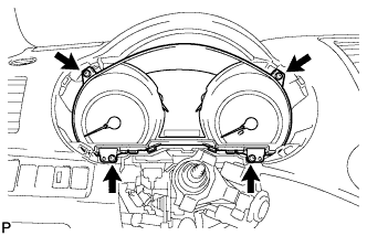
Remove the 4 screws <F>.
-
Disconnect the connector and remove the combination meter assembly.
-
- Click here
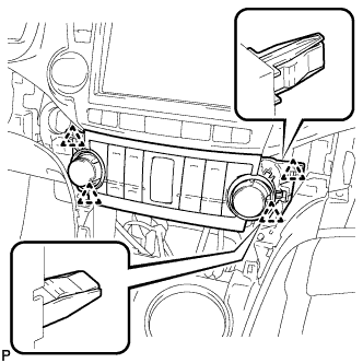
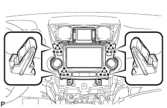
REMOVE CENTER INSTRUMENT PANEL REGISTER ASSEMBLY
-
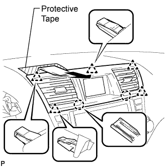
Apply protective tape to the areas shown in the illustration.
-
Using a moulding remover, disengage the 2 claws and 5 clips, and then remove the center instrument panel register assembly as shown in the illustration.
-
- Click here
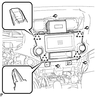
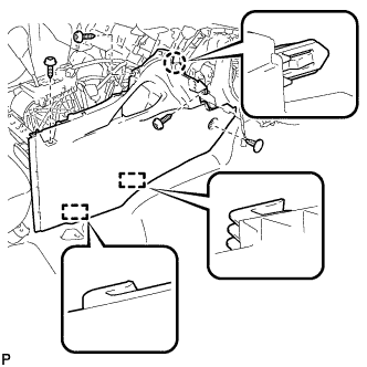
REMOVE CENTER INSTRUMENT CLUSTER FINISH PANEL ASSEMBLY (w/o Smart Entry and Start System)
-
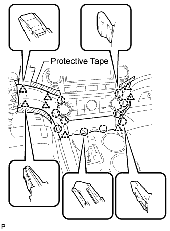
Apply protective tape to the areas shown in the illustration.
-
Using a moulding remover, disengage the 10 claws and 8 clips starting from the upper part of the center instrument cluster finish panel assembly.
Note:Do not pull on the small storage compartment lid. Doing so may cause damage.
-
Disconnect each connector and remove the center instrument cluster finish panel assembly.
-
- Click here
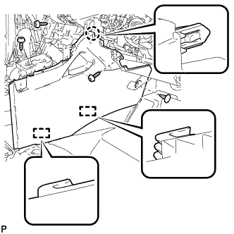
REMOVE CENTER INSTRUMENT CLUSTER FINISH PANEL ASSEMBLY (w/ Smart Entry and Start System)
-
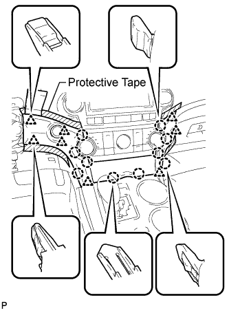
Apply protective tape to the areas shown in the illustration.
-
Using a moulding remover, disengage the 10 claws and 8 clips starting from the upper part of the center instrument cluster finish panel assembly.
Note:Do not pull on the small storage compartment lid. Doing so may cause damage.
-
Disconnect each connector and remove the center instrument cluster finish panel assembly.
-
- Click here
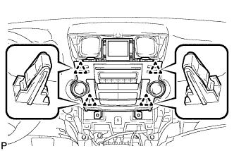
REMOVE HEATER CONTROL AND ACCESSORY ASSEMBLY (for Manual Air Conditioning System)
-

Disengage the 4 clips and remove the heater control and accessory assembly.
-
Disconnect the connector.
-
- Click here
REMOVE AIR CONDITIONING CONTROL ASSEMBLY (for Automatic Air Conditioning System)
-
Disengage the 4 clips and remove the air conditioning control assembly.
-
Disconnect the connector.
-
- Click here
REMOVE RADIO RECEIVER ASSEMBLY WITH BRACKET (w/o Navigation System)
-
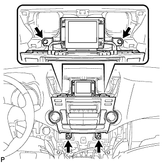
Remove the 4 bolts.
-
Pull the radio receiver assembly with bracket toward the rear of the vehicle and disengage the 4 clips.
-
Disconnect each connector and remove the radio receiver assembly with bracket.
-
- Click here
REMOVE NAVIGATION RECEIVER ASSEMBLY WITH BRACKET (w/ Navigation System)
-
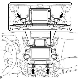
Remove the 4 bolts.
-
Pull the navigation receiver assembly with bracket toward the rear of the vehicle and disengage the 4 clips.
-
Disconnect each connector and remove the navigation receiver assembly with bracket.
-
- Click here
REMOVE INTEGRATION CONTROL AND PANEL ASSEMBLY WITH BRACKET (w/o Radio Receiver)
-
Remove the 4 bolts <D>.
-
Disengage the 4 clips.
-
Disconnect each connector and remove the integration control and panel assembly with bracket.
-
- Click here
REMOVE FRONT DOOR SCUFF PLATE LH
-

Disengage the 8 claws and guide, and remove the front door scuff plate LH.
-
- Click here
REMOVE COWL SIDE TRIM SUB-ASSEMBLY LH
-

Remove the clip.
-
Disengage the clip and claw, and remove the cowl side trim sub-assembly LH.
-
- Click here
REMOVE LOWER INSTRUMENT PANEL FINISH PANEL SUB-ASSEMBLY (for Manual Air Conditioning System)
-

Remove the 2 bolts <B>.
-
Disengage the 3 claws and 10 clips.
-
Disconnect each connector.
-
Disconnect the hood lock control cable assembly and remove the lower instrument panel finish panel sub-assembly.
-
- Click here
REMOVE LOWER INSTRUMENT PANEL FINISH PANEL SUB-ASSEMBLY (for Automatic Air Conditioning System)
-

Remove the 2 bolts <B>.
-
Disengage the 3 claws and 10 clips.
-

Disconnect each connector and the aspirator duct.
-
Disconnect the hood lock control cable assembly and remove the lower instrument panel finish panel sub-assembly.
-
- Click here
REMOVE FRONT DOOR SCUFF PLATE RH
Tip:Use the same procedure for the RH side and the LH side.
- Click here
REMOVE COWL SIDE TRIM SUB-ASSEMBLY RH
Tip:Use the same procedure for the RH side and the LH side.
- Click here
REMOVE NO. 2 INSTRUMENT PANEL UNDER COVER SUB-ASSEMBLY
-
Disengage the 3 claws.
-
Disengage the 2 guides and remove the No. 2 instrument panel under cover sub-assembly.
-
- Click here
REMOVE LOWER INSTRUMENT PANEL SUB-ASSEMBLY
-
Remove the 2 bolts <B> and 3 screws <F>.
-
Disengage the 4 claws and 3 clips.
-
Disconnect each connector and clamp, and remove the lower instrument panel sub-assembly.
-
- Click here
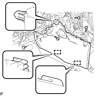
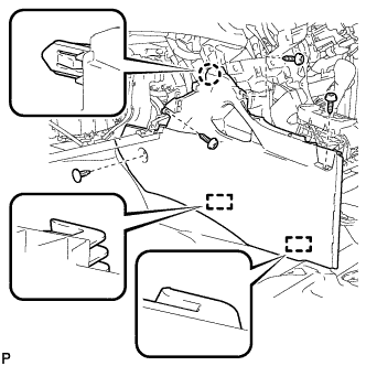
REMOVE UPPER CONSOLE PANEL SUB-ASSEMBLY
-
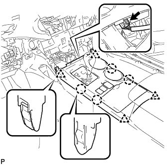
Disengage the 4 claws and 4 clips.
-
Disconnect the connector and remove the upper console panel sub-assembly.
-
- Click here
REMOVE NO. 2 CONSOLE BOX DUCT (w/o Rear Air Conditioning System)
-
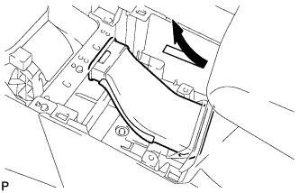
Remove the No. 2 console box duct as shown in the illustration.
-
- Click here
REMOVE LOWER REAR CONSOLE BOX
-
Remove the lower rear console box.
-
- Click here
REMOVE CONSOLE BOX ASSEMBLY (w/o Rear Air Conditioning System)
-
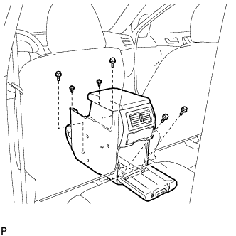
Remove the 4 bolts and 2 screws.
-
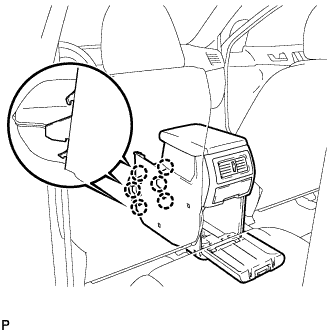
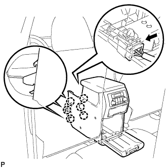
Disengage the 6 claws and remove the console box assembly.
-
- Click here
REMOVE CONSOLE BOX ASSEMBLY (w/ Rear Air Conditioning System)
-
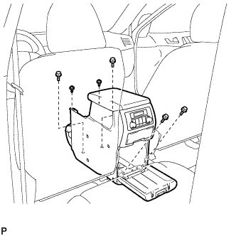
Remove the 4 bolts and 2 screws.
-
Disconnect the connector.
-
Disengage the 6 claws, and remove the console box assembly.
-
- Click here
REMOVE FRONT NO. 1 CONSOLE BOX INSERT (for LHD)
-
Using a clip remover, remove the 2 clips.
-
Remove the 3 screws <F>.
-
Disengage the claw and 2 guides, and then remove the front No. 1 console box insert.
-
- Click here
REMOVE FRONT NO. 1 CONSOLE BOX INSERT (for RHD)
-
Using a clip remover, remove the clip.
-
Remove the 3 screws <F>.
-
Disengage the claw and 2 guides, and then remove the front No. 1 console box insert.
-
- Click here
REMOVE FRONT NO. 2 CONSOLE BOX INSERT (for LHD)
-
Using a clip remover, remove the clip.
-
Remove the 3 screws <F>.
-
Disengage the claw and 2 guides, and then remove the front No. 2 console box insert.
-
- Click here
REMOVE FRONT NO. 2 CONSOLE BOX INSERT (for RHD)
-
Using a clip remover, remove the clip.
-
Remove the 3 screws <F>.
-
Disengage the claw and 2 guides, and then remove the front No. 2 console box insert.
-
- Click here
REMOVE ENGINE SWITCH (w/ Smart Entry and Start System)
-
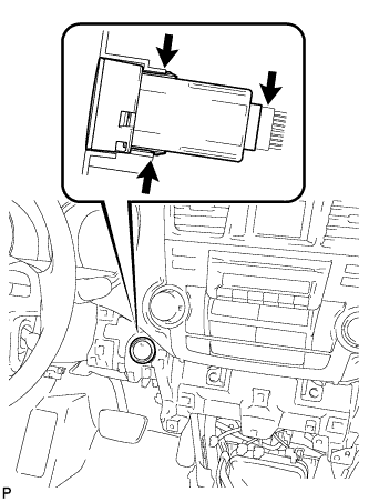
Disconnect the switch connector.
-
Disengage the 2 claws and remove the switch.
-
- Click here
DISCONNECT FRONT DOOR OPENING TRIM WEATHERSTRIP LH
-
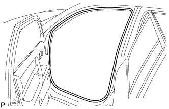
Remove the front door opening trim weatherstrip LH.
-
- Click here
REMOVE FRONT PILLAR GARNISH LH
-
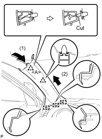
Pull the upper part of the garnish toward the inside of the cabin and disengage the 2 clips.
-
Cut off the clip <A>.
-
Disengage the 3 guides and remove the front pillar garnish LH.
-
Remove the clip <A>.
-
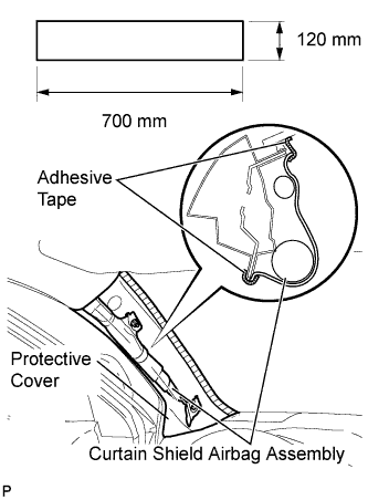
Protect the curtain shield airbag assembly.
-
Cover the airbag with a 700 mm (27.56 in.) x 120 mm (4.72 in.) cloth or piece of nylon and fix the ends of the cover with tape, as shown in the illustration.
Note:Cover the curtain shield airbag with a protective cover as soon as the front pillar garnish is removed.
-
-
- Click here
DISCONNECT FRONT DOOR OPENING TRIM WEATHERSTRIP RH
Tip:Use the same procedure for the RH side and the LH side.
- Click here
REMOVE FRONT PILLAR GARNISH RH
-
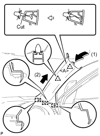
Pull the upper part of the garnish toward the inside of the cabin and disengage the 2 clips.
-
Cut off the clip <A>.
-
Disengage the 3 guides and remove the front pillar garnish RH.
-
Remove the clip <A>.
-
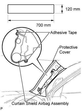
Protect the curtain shield airbag assembly.
-
Cover the airbag with a 700 mm (27.56 in.) x 120 mm (4.72 in.) cloth or piece of nylon and fix the ends of the cover with tape, as shown in the illustration.
Note:Cover the curtain shield airbag with a protective cover as soon as the front pillar garnish is removed.
-
-
- Click here
REMOVE NO. 1 INSTRUMENT PANEL SPEAKER PANEL SUB-ASSEMBLY
-
Disengage the 2 claws and 2 clips.
-
Disengage the 2 guides and remove the No. 1 instrument panel speaker panel sub-assembly.
-
- Click here
REMOVE FRONT NO. 2 SPEAKER ASSEMBLY (for LH Side)
-
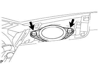
Remove the 2 bolts and front No. 2 speaker assembly.
-
Disconnect the connector.
-
- Click here
REMOVE NO. 2 INSTRUMENT PANEL SPEAKER PANEL SUB-ASSEMBLY
-
Disengage the 2 claws and 2 clips.
-
Disengage the 2 guides and remove the No. 2 instrument panel speaker panel sub-assembly.
-
- Click here
REMOVE FRONT NO. 2 SPEAKER ASSEMBLY (for RH Side)
Tip:Use the same procedures for the RH side and the LH side.
- Click here
DISCONNECT INSTRUMENT PANEL WIRE ASSEMBLY
-
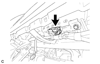
Disconnect the connector.
-
- Click here
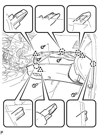
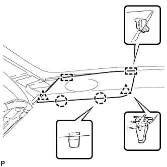
REMOVE INSTRUMENT PANEL SAFETY PAD ASSEMBLY (for Pole Antenna Type)
-
Disconnect each connector.
-
Remove the bolt <E>.
-
Remove the 2 passenger airbag bolts <A>.
-
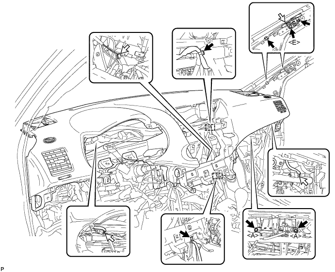
Disengage each clamp.
-
Remove the 2 clips.
-
Remove the 2 bolts <D> and nut <H>.
-
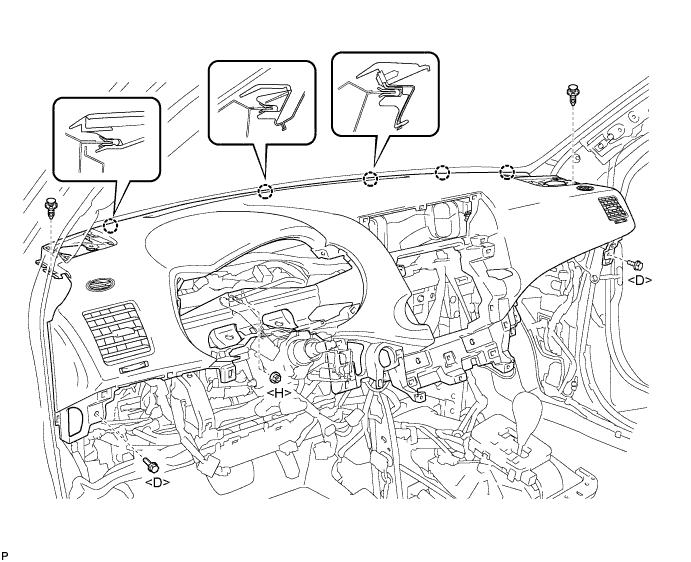
Disengage the 5 claws and remove the instrument panel safety pad assembly.
-
- Click here
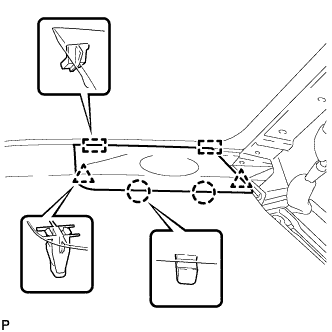
REMOVE INSTRUMENT PANEL SAFETY PAD ASSEMBLY (for Glass Antenna Type)
-
Disconnect each connector.
-
Remove the 2 passenger airbag bolts <A>.
-
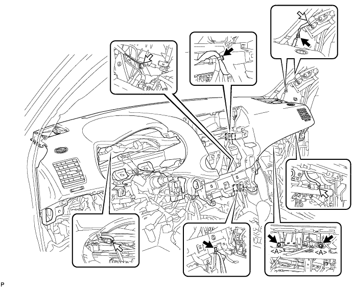
Disengage each clamp.
-
Remove the 2 clips.
-
Remove the 2 bolts <D> and nut <H>.
-
Disengage the 5 claws and remove the instrument panel safety pad assembly.
-
- Click here
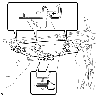
REMOVE NO. 3 INSTRUMENT PANEL STAY
-
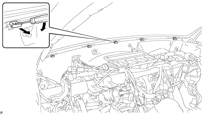
Using a screwdriver, disengage the claw and remove the 5 No. 3 instrument panel stays as shown in the illustration.
-
- Click here
REMOVE CONSOLE BOX CUP HOLDER
-
Remove the 2 console box cup holders.
-
- Click here
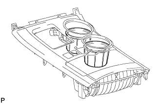
REMOVE INSTRUMENT PANEL CUP HOLDER ASSEMBLY
-
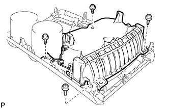
Remove the 4 screws <G> and the instrument panel cup holder assembly.
-
- Click here
REMOVE NO. 2 CONSOLE BOX CUP HOLDER
-
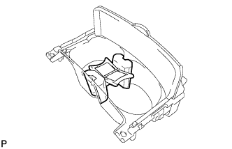
Remove the No. 2 console box cup holder.
-