WINDOW DEFOGGER SYSTEM Rear Window Defogger System does not Operate
DESCRIPTION
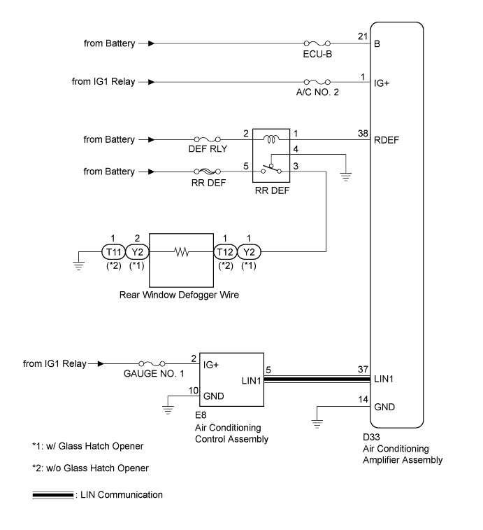
When the rear window defogger switch, which is built into the air conditioning control assembly, is operated, the operation signals are transmitted to the air conditioning amplifier assembly through LIN. When the air conditioning amplifier assembly receives the signals, it turns on the DEFOGGER relay (Marking: RR DEF) to operate the rear window defogger.
WIRING DIAGRAM
INSPECTION PROCEDURE
PROCEDURE
-
CHECK FUSES (RR DEF)
-
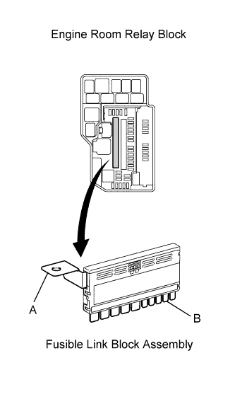
Remove the fusible link block assembly (RR DEF) from the engine room relay block.
-
Measure the resistance according to the value(s) in the table below.
Standard resistance Tester Connection Condition Specified Condition A - B (RR DEF) Always Below 1 Ω
NG 
REPLACE ENGINE ROOM JUNCTION BLOCK (RR DEF FUSE)
OK 
-
-
INSPECT DEFOGGER RELAY (Marking: RR DEF)
-
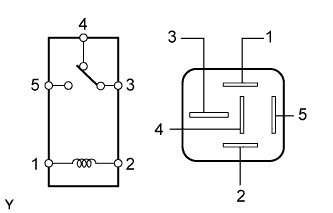
Remove the defogger relay (Marking: RR DEF) from the engine room relay block.
-
Measure the resistance according to the value(s) in the table below.
Standard resistance Tester Connection Condition Specified Condition 3 - 4 Voltage is not applied between terminals 1 and 2 Below 1 Ω 3 - 4 Apply battery voltage between terminals 1 and 2 10 kΩ or higher 3 - 5 Voltage is not applied between terminals 1 and 2 10 kΩ or higher 3 - 5 Apply battery voltage between terminals 1 and 2 Below 1 Ω
NG
REPLACE DEFOGGER RELAY (Marking: RR DEF)
OK
-
-
PERFORM ACTIVE TEST USING INTELLIGENT TESTER
-
Select the ACTIVE TEST, use the intelligent tester to issue a control command, and then check the window defogger operation.
Air Conditioner: Tester Display Test Part Control Range Diagnostic Note Defogger Relay (Rear) Rear window defogger OFF/ON - Result Result Proceed to The window defogger system does not operate normally when operating it through the intelligent tester. A The window defogger system operates normally when operating it through the intelligent tester. B
A 
PERFORM ACTIVE TEST USING INTELLIGENT TESTER Click here
B
-
-
CHECK HARNESS AND CONNECTOR (LIN COMMUNICATION LINE)
-
Disconnect the D33 air conditioning amplifier connector.
-
Disconnect the E8 air conditioning control connector.
-
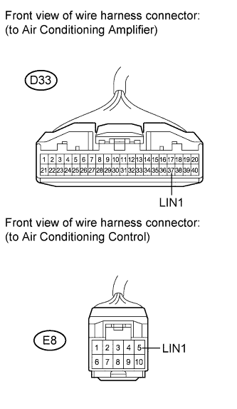
Measure the resistance according to the value(s) in the table below.
Standard resistance Tester Connection Condition Specified Condition D33-37 (LIN1) - E8-5 (LIN1) Always Below 1 Ω D33-37 (LIN1) - Body ground Always 10 kΩ or higher
NG
REPAIR OR REPLACE HARNESS OR CONNECTOR
OK
-
-
REPLACE AIR CONDITIONING CONTROL ASSEMBLY
-
for Automatic Air Conditioning System
-
Replace the air conditioning control assembly Click here.
-
-
for Manual Air Conditioning System
-
Replace the air conditioning control assembly Click here.
-
NEXT
-
-
CONFIRM REAR WINDOW DEFOGGER OPERATION
-
Turn the ignition switch on (IG), press the defogger switch, and check that the window defogger operates.
OK Window defogger system operates normally.
NG
REPLACE AIR CONDITIONING AMPLIFIER ASSEMBLY Click here
OK 
REPLACE DEFOGGER RELAY (Marking: RR DEF)
-
-
PERFORM ACTIVE TEST USING INTELLIGENT TESTER
-
Select the ACTIVE TEST, use the intelligent tester to issue a control command, and then check the window defogger operation.
Air Conditioner: Tester Display Test Part Control Range Diagnostic Note Defogger Relay (Rear) Rear window defogger OFF/ON - -
Check that operation sound of the DEFOGGER relay (Marking: RR DEF) is heard.
Result Result Proceed to Relay operating sound is heard A Relay operating sound is not heard B
A
CHECK HARNESS AND CONNECTOR (REAR WINDOW DEFOGGER WIRE - ENGINE ROOM RELAY BLOCK) Click here
B
-
-
CHECK HARNESS AND CONNECTOR (A/C AMPLIFIER ASSEMBLY - ENGINE ROOM RELAY BLOCK)
-
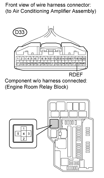
Disconnect the D33 air conditioning amplifier connector.
-
Disconnect the defogger relay (Marking: RR DEF) from the engine room relay block.
-
Measure the resistance according to the value(s) in the table below.
Standard resistance Tester Connection Condition Specified Condition D33-38 (RDEF) - 2 Always Below 1 Ω D33-38 (RDEF) - Body ground Always 10 kΩ or higher
NG
REPAIR OR REPLACE HARNESS OR CONNECTOR
OK
-
-
CHECK HARNESS AND CONNECTOR (RDEF TERMINAL BATTERY VOLTAGE)
-
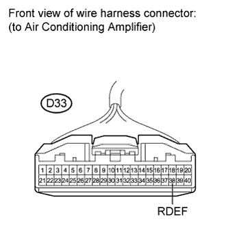
Reconnect the defogger relay (Marking: RR DEF) from the engine room relay block.
-
Measure the voltage according to the value(s) in the table below.
Standard voltage Tester Connection Condition Specified Condition D33-38 (RDEF) - Body ground Ignition switch on (IG) 11 to 14 V
NG
PROCEED TO NEXT CIRCUIT INSPECTION SHOWN IN PROBLEM SYMPTOMS TABLE Click here
OK
REPLACE AIR CONDITIONING AMPLIFIER ASSEMBLY Click here
-
-
CHECK HARNESS AND CONNECTOR (REAR WINDOW DEFOGGER WIRE - ENGINE ROOM RELAY BLOCK)
-
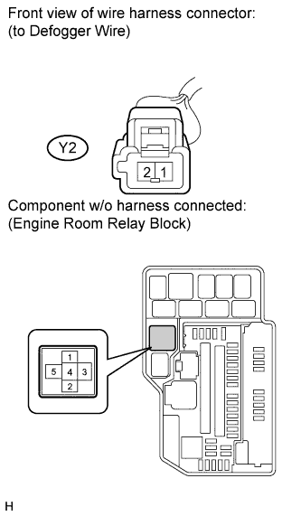
w/ Glass Hatch Opener:
-
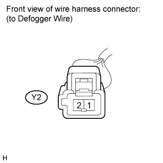
Disconnect the Y2 connector.
-
Remove the defogger relay (Marking: RR DEF) from the engine room relay block.
-
Measure the resistance according to the value(s) in the table below.
Standard resistance Tester Connection Condition Specified Condition Y2-1 - 3 Always Below 1 Ω Y2-1 - Body ground Always 10 kΩ or higher
-
-
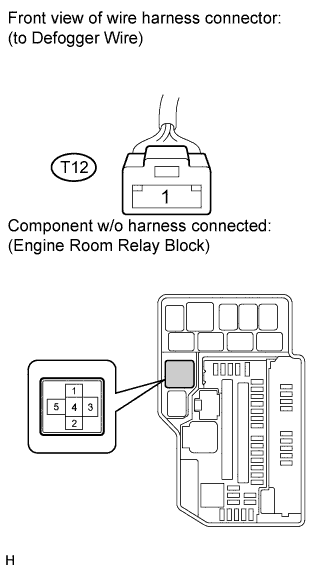
w/o Glass Hatch Opener:
-
Disconnect the T12 connector.
-
Remove the defogger relay (Marking: RR DEF) from the engine room relay block.
-
Measure the resistance according to the value(s) in the table below.
Standard resistance Tester Connection Condition Specified Condition T12-1 - 3 Always Below 1 Ω T12-1 - Body ground Always 10 kΩ or higher
-
NG
REPAIR OR REPLACE HARNESS OR CONNECTOR
OK
-
-
CHECK HARNESS AND CONNECTOR (REAR WINDOW DEFOGGER WIRE CONNECTOR - BODY GROUND)
-
w/ Glass Hatch Opener:
-
Disconnect the Y2 connector.
-
Measure the resistance according to the value(s) in the table below.
Standard resistance Tester Connection Condition Specified Condition Y2-2 - Body ground Always Below 1 Ω
-
-
w/o Glass Hatch Opener:
-
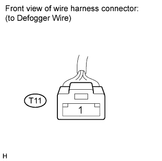
Disconnect the T11 connector.
-
Measure the resistance according to the value(s) in the table below.
Standard resistance Tester Connection Condition Specified Condition T11-1 - Body ground Always Below 1 Ω
-
NG
REPAIR OR REPLACE HARNESS OR CONNECTOR
OK
REPAIR OR REPLACE REAR WINDOW DEFOGGER WIRE
-