WINDOW DEFOGGER SYSTEM TERMINALS OF ECU
-
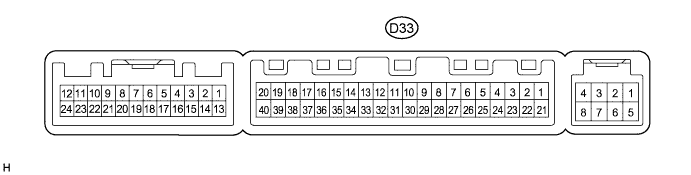
CHECK AIR CONDITIONING AMPLIFIER ASSEMBLY
-
Measure the voltage and resistance according to the value(s) in the table below.
Standard voltage Tester Connection Wiring Color Terminal Description Condition Specified Condition D33-38 (RDEF) - D33-14 (GND) W - W-B Rear defogger signal Ignition switch on (IG), Rear window defogger switch OFF 11 to 14 V Ignition switch on (IG), Rear window defogger switch ON Below 1 V D33-1 (IG+) - D33-14 (GND) GR - W-B Power source (IG) Ignition switch on (IG) 11 to 14 V Ignition switch off Below 1 V D33-21 (B) - D33-14 (GND) B - W-B Power source (Back-up) Always 11 to 14 V Standard resistance Tester Connection Wiring Color Terminal Description Condition Specified Condition D33-14 (GND) - Body ground W-B - Body ground Ground Always Below 1 Ω If the result is not as specified, there may be a malfunction in the wire harness or amplifier.
-
-
CHECK AIR CONDITIONING CONTROL ASSEMBLY

-
Measure the voltage and resistance according to the value(s) in the table below.
Standard voltage Tester Connection Wiring Color Terminal Description Condition Specified Condition E8-2 (IG+) - E8-10 (GND) V - GR Power source (IG) Ignition switch on (IG) 11 to 14 V Standard resistance Tester Connection Wiring Color Terminal Description Condition Specified Condition E8-10 (GND) - Body ground GR - Body ground Ground Always Below 1 Ω If the result is not as specified, there may be a malfunction in the wire harness.
-