WINDSHIELD GLASS INSTALLATION
-
INSTALL NO. 2 WINDSHIELD GLASS STOPPER
-
Using a brush or sponge, coat the application area of the No. 2 windshield glass stoppers with Primer G.
Note
-
Do not apply too much primer.
-
Allow the primer to dry for 3 minutes or more.
-
Throw away any leftover Primer G.
Tech Tips
If an area other than that specified is coated by accident, wipe off the primer with a clean piece of cloth before it dries.
-
-
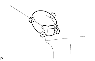
Install 2 new No. 2 windshield glass stoppers onto the glass as shown in the illustration.
Note
Only 2-piece type No. 2 windshield glass stoppers are supplied. Use the 2-piece type stoppers even if a 1-piece type was originally installed.
-
-
INSTALL NO. 1 WINDSHIELD GLASS STOPPER
-
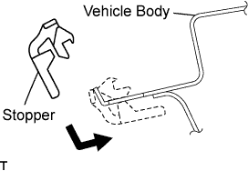
Install 2 new No. 1 windshield glass stoppers to the vehicle body, as shown in the illustration.
Note
Only 2-piece type No. 1 windshield glass stoppers are supplied. Use the 2-piece type stoppers even if a 1-piece type was originally installed.
-
-
INSTALL WINDOW GLASS ADHESIVE DAM
-
Using a brush or sponge, coat the application area of the window glass adhesive dam with Primer G.
Note
-
Do not apply too much primer.
-
Allow the primer coating to dry for 3 minutes or more.
-
Throw away any leftover Primer G.
-
-
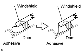
Install a new window glass adhesive dam onto the windshield glass, as shown in the illustration.
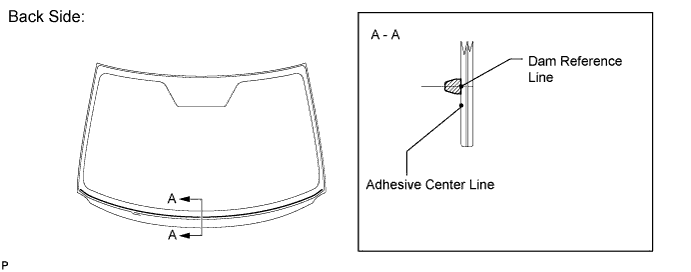
Note
Install the new adhesive dam along the dam reference line.
-
-
INSTALL WINDSHIELD GLASS
-
Position the windshield glass.
-
Using suction cups, place the glass in the correct position.
-
Check that the entire contact surface of the glass rim is perfectly even.
-
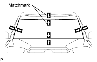
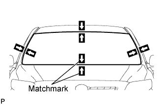
Place matchmarks on the glass and vehicle body on the locations indicated in the illustration.
Tech Tips
-
Placing matchmarks is necessary only when installing a new glass. If it is the reused glass, matchmarks should already be present.
-
When reusing the glass, check and correct the matchmark positions.
Note
Check that the stoppers are attached to the vehicle body correctly.
-
-
Using suction cups, remove the glass.
-
-
Using a brush, apply Primer M to the exposed part of the vehicle body.
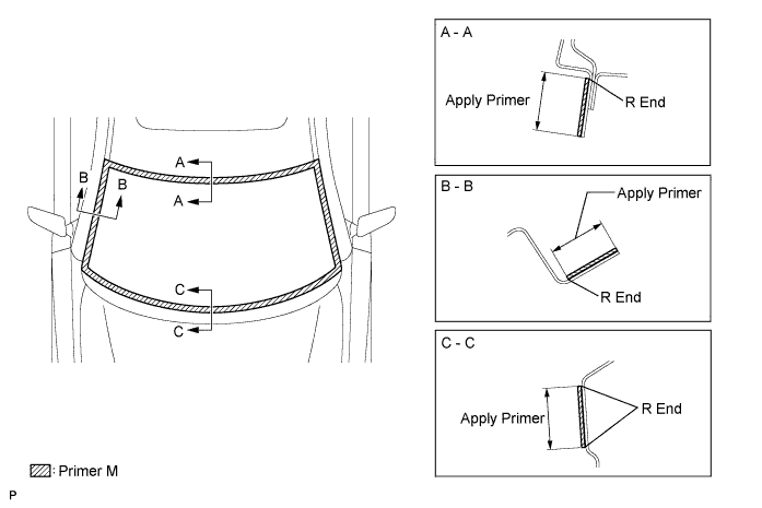
Note
-
Allow the primer to dry for 3 minutes or more.
-
Do not apply primer to the adhesive.
-
Throw away any leftover Prime M.
-
Do not apply too much primer.
-
-
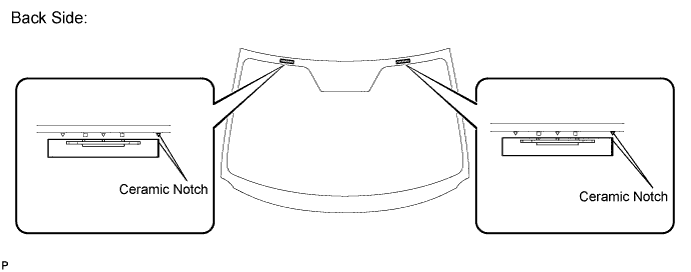
Using a brush or sponge, coat the application area of adhesive with Primer G.
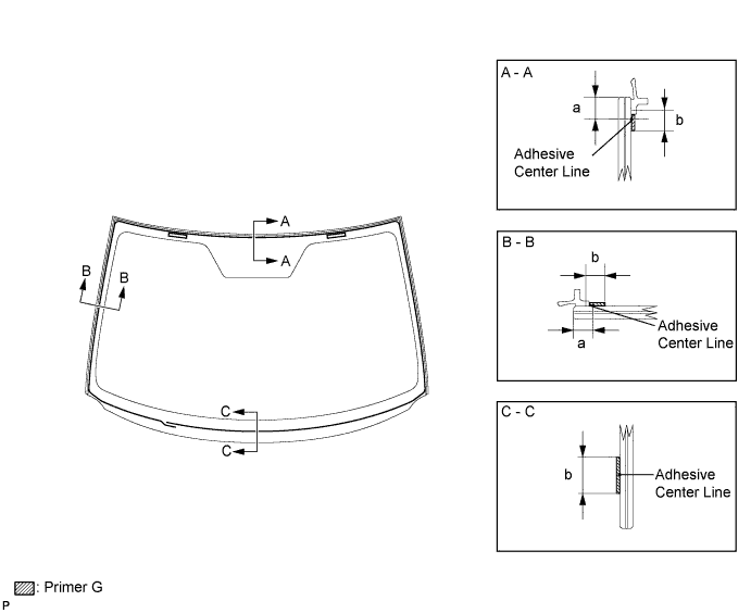
Standard dimension Area Dimension a 8.6 mm (0.338 in.) b 8.0 mm (0.315 in.) Note
-
Do not apply too much primer.
-
Allow the primer to dry for 3 minutes or more.
-
Throw away any leftover Primer G.
Tech Tips
-
Apply Primer G onto the ceramic notches.
-
If an area other than that specified is coated by accident, wipe off the primer with a clean piece of cloth before it dries.
-
-
Apply adhesive to the glass.
Adhesive Toyota Genuine Windshield Glass Adhesive or equivalent
-
Cut off the tip of the cartridge nozzle as shown in the illustration.
Tech Tips
After cutting off the tip, use all adhesive within the time written in the table below.
Usage time frame Temperature Usage Time Frame 35°C (95°F) 15 minutes 20°C (68°F) 1 hour and 40 minutes 5°C (41°F) 8 hours -
Load the sealer gun with the cartridge.
-
Apply adhesive to the glass as shown in the illustration.
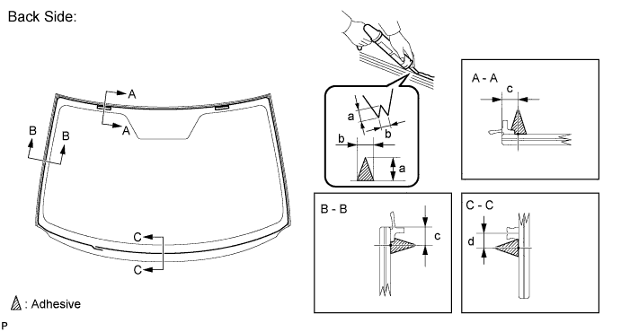
Standard dimension Area Dimension a 12.0 mm (0.472 in.) b 8.0 mm (0.315 in.) c 8.6 mm (0.338 in.) d 6.5 mm (0.256 in.) Tech Tips
Apply adhesive onto the ceramic notches.
-
-
Install the windshield glass assembly.
-
Using suction cups, position the glass so that the matchmarks are aligned. Press it in gently along the rim.
-
Lightly press the outer surface of the glass to ensure that it is securely fitted to the vehicle body.
Note
-
Check that the windshield glass stoppers are attached to the vehicle body correctly.
-
Check the clearance between the vehicle body and windshield glass.
Tech Tips
Press the glass with force of 98 N (10 kgf, 22 lbf) or more.
-
-
If necessary, use a scraper to correct the level or position of adhesive that has been applied.
Note
Apply adhesive onto the windshield glass rim.
-
Hold the windshield glass using protective tape until applied adhesive becomes hard.
Note
Do not drive the vehicle for the time described in the table below.
Minimum time Temperature Usage Time Frame 35°C (95°F) 1 hour and 30 minutes 5°C (41°F) 24 hours 20°C (68°F) 5 hours
-
-
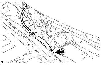
Engage the connector and clamp. (w/ Deicer)
-
-
INSPECT FOR LEAK AND REPAIR
-
After the adhesive has hardened, apply water from the outside of the vehicle. Check that no water leaks into the cabin.
-
If water leaks into the cabin, allow the water to dry and add adhesive.
-
Remove the protective tape.
-
-
INSTALL ROOF HEADLINING ASSEMBLY
Return the front section of the roof headlining assembly to the original position.
-
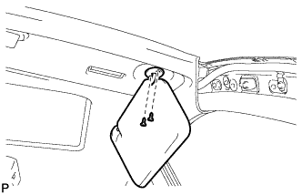
INSTALL VISOR HOLDER
-
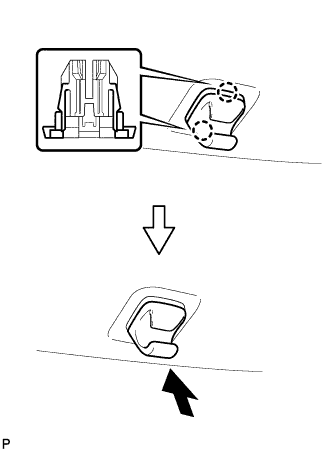
Engage the 2 claws.
-
Push in the visor holder as shown in the illustration.
Tech Tips
Use the same procedure for the RH side and the LH side.
-
-
INSTALL ASSIST GRIP ASSEMBLY (w/ Sliding Roof)
-
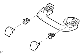
Assemble the rear assist grip assembly as shown in the illustration.
-
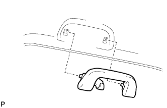
Install the rear assist grip sub-assembly.
Tech Tips
Use the same procedure for the RH side and the LH side.
-
-
INSTALL FRONT ASSIST GRIP SUB-ASSEMBLY (w/o Sliding Roof)
-
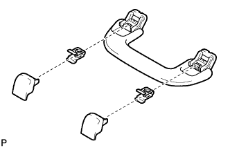
Assemble the front assist grip sub-assembly as shown in the illustration.
-
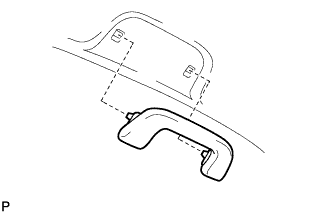
Install the front assist grip sub-assembly.
Tech Tips
Use the same procedure for the other 3 assist grips.
-
-
INSTALL VISOR ASSEMBLY LH
-
Install the visor assembly LH with the 2 screws.
-
-
INSTALL VISOR BRACKET COVER (for LH Side)
-
Engage the 4 claws and install the visor bracket cover.
-
-
INSTALL VISOR ASSEMBLY RH
Tech Tips
Use the same procedure for the RH side and the LH side.
-
INSTALL VISOR BRACKET COVER (for RH Side)
Tech Tips
Use the same procedure for the RH side and the LH side.
-
INSTALL ROOF CONSOLE BOX ASSEMBLY
-
Connect the connector.
-
Engage the 3 guides, 2 clips, fastener, and install the roof console box assembly.
-
-
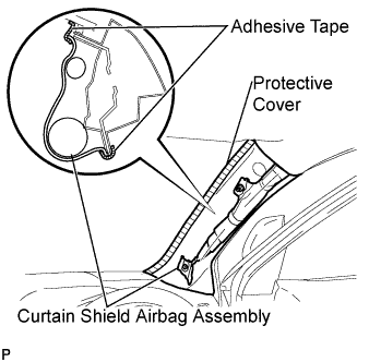
INSTALL FRONT PILLAR GARNISH LH
-
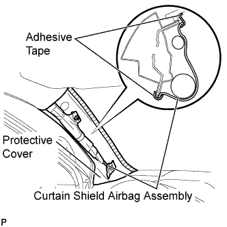
Remove the protective cover.
-
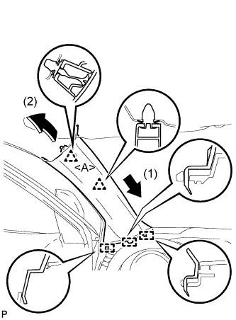
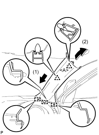
Install a new clip <A> on the front pillar garnish LH.
-
Engage the 3 guides and 2 clips, then install the front pillar garnish LH.
-
-
INSTALL FRONT PILLAR GARNISH RH
-
Remove the protective cover.
-
Install a new clip <A> on the front pillar garnish RH.
-
Engage the 3 guides and 2 clips, then install the front pillar garnish RH.
-
-
INSTALL COWL TOP VENTILATOR LOUVER SUB-ASSEMBLY
-
Engage the 20 claws.
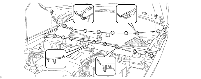
-
Install the cowl top ventilator louver with the 2 clips.
-
-
INSTALL FRONT FENDER TO COWL SIDE SEAL LH
-
Engage the claw and install a new front fender to cowl side seal LH.
-
Engage the 2 claws.
-
-
INSTALL FRONT FENDER TO COWL SIDE SEAL RH
Tech Tips
Use the same procedure for the RH side and the LH side.
-
INSTALL FRONT WIPER ARM AND BLADE ASSEMBLY RH
-
Operate the wiper and stop the windshield wiper motor at the automatic stop position.
-
When reinstalling:
-
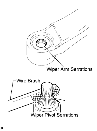
Clean the wiper arm serrations.
-
Clean the wiper pivot serrations with a wire brush.
-
-
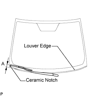
Install the front wiper arm and blade assembly RH with the nut to the position shown in the illustration.
- Torque:
- 24 N*m { 245 kgf*cm, 18 ft.*lbf }
Tech Tips
Hold the wiper arm by hand when tightening the nut.
Area Measurement A 25.6 mm (1.00 in.)
-
-
INSTALL FRONT WIPER ARM AND BLADE ASSEMBLY LH
-
Operate the wiper and stop the windshield wiper motor at the automatic stop position.
-
When reinstalling:
-
Clean the wiper arm serrations.
-
Clean the wiper pivot serrations with a wire brush.
-
-
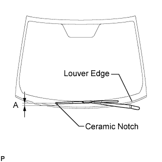
Install the front wiper arm and blade assembly LH with the nut to the position shown in the illustration.
- Torque:
- 24 N*m { 245 kgf*cm, 18 ft.*lbf }
Tech Tips
Hold the wiper arm by hand when tightening the nut.
Area Measurement A 31.9 mm (1.26 in.) -
Operate the front wipers while spraying washer fluid onto the windshield glass. Make sure that the front wipers function properly and the wipers do not come into contact with the vehicle body.
-
-
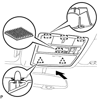
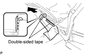
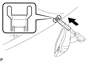
INSTALL INNER REAR VIEW MIRROR ASSEMBLY (w/o EC Mirror)
-
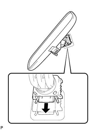
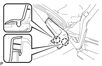
Slide the inner rear view mirror assembly in the direction indicated by the arrow shown in the illustration to install it.
-
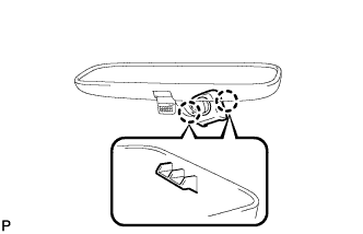
Engage the 2 claws and install the cover.
-
-
INSTALL INNER REAR VIEW MIRROR ASSEMBLY (w/ EC Mirror)
-
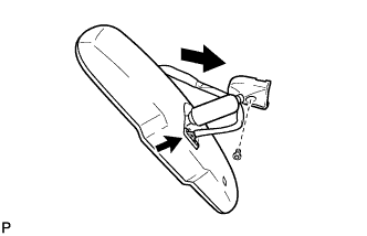
Using a "TORX" socket wrench (T20), install the inner rear view mirror with the screw.
- Torque:
- 3.5 N*m { 36 kgf*cm, 31 in.*lbf }
-
-
INSTALL INNER REAR VIEW MIRROR STAY HOLDER COVER (w/ EC Mirror)
-
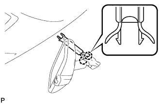
Engage the 2 claws and install the inner rear view mirror stay holder cover.
-
Engage the 2 claws and install the inner rear view mirror stay holder cover as shown in the illustration.
-