| DTC Code | DTC Name |
|---|---|
| Glass Hatch Opener System does not Operate |
DESCRIPTION
The glass hatch opener system enables the back door glass to be opened when the glass hatch opener switch is pressed.
INSPECTION PROCEDURE
PROCEDURE
- Click here
SYSTEM CHECK
-
Confirm that the vehicle is equipped with the smart entry and start system.
Result Result Proceed to w/ Smart Entry and Start System A w/o Smart Entry and Start System B
-
- Click here
CHECK SMART ENTRY AND START SYSTEM
-
When the back door entry lock switch is operated, check that the back door lock.
OK Back door entry lock function operates normally.
- OKClick here
- NGClick here
-
- Click here
PERFORM ACTIVE TEST USING INTELLIGENT TESTER
-
Connect the intelligent tester to the DLC3.
-
Turn the ignition switch on (IG) and turn the intelligent tester main switch on.
-
Select the item below in the ACTIVE TEST and then check that the relay operates.
Table 1. Main Body (Main Body ECU): Tester Display Test Part Control Range Diagnostic Note Glass Hatch Open Operate Glass Hatch ON or OFF - OK Glass hatch operates.
- OKClick here
- NGClick here
-
- Click here
READ VALUE USING INTELLIGENT TESTER (GLASS HATCH COURTESY SWITCH)
-
Connect the intelligent tester to the DLC3.
-
Turn the ignition switch on (IG) and turn the intelligent tester main switch on.
-
Select the items below in the DATA LIST, and read the displays on the intelligent tester.
Table 2. Main Body (Main Body ECU): Tester Display Measurement Item/Range Normal Condition Diagnostic Note Glass Hatch Courtesy Switch Glass hatch courtesy switch signal / ON or OFF ON: Glass hatch is open
OFF: Glass hatch is closed
- OK Normal conditions listed above are displayed.
- OKClick here
- NGClick here
-
- Click here
READ VALUE USING INTELLIGENT TESTER (GLASS HATCH OPENER SWITCH)
-
Connect the intelligent tester to the DLC3.
-
Turn the ignition switch on (IG) and turn the intelligent tester main switch on.
-
Select the items below in the DATA LIST, and read the displays on the intelligent tester.
Table 3. Main Body (Main Body ECU): Tester Display Measurement Item/Range Normal Condition Diagnostic Note Glass Hatch Opener Switch Glass Hatch Opener Switch signal / ON or OFF ON: Glass hatch opener switch operates
OFF: Glass hatch opener switch does not operate
- OK Normal conditions listed above are displayed.
- OKClick here
- NGClick here
-
- Click here
REPLACE MAIN BODY ECU (INSTRUMENT PANEL JUNCTION BLOCK)
- Click here
GO TO SMART ENTRY AND START SYSTEMClick here
- Click here
INSPECT BACK WINDOW LOCK ASSEMBLY
-
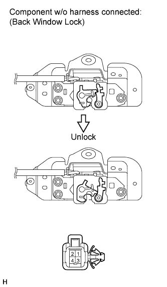
Measure the resistance according to the value(s) in the table below.
Standard resistance Tester Connection Condition Specified Condition 1 - 2 Voltage is not applied between terminals 3 and 4 10 kΩ or higher 1 - 2 Apply battery voltage between terminals 3 and 4 Below 1 Ω If the result is not as specified, replace the back window lock assembly.
- OKClick here
- NGClick here
-
- Click here
INSPECT GLASS HATCH OPENER SWITCH ASSEMBLY
-
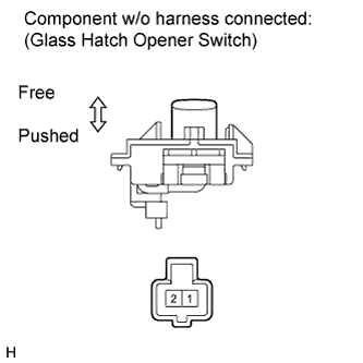
Measure the resistance according to the value(s) in the table below.
Standard resistance Tester Connection Condition Specified Condition 1 - 2 Switch free 10 kΩ or higher 1 - 2 Switch pushed Below 1 Ω If the result is not as specified, replace the glass hatch opener switch assembly.
- OKClick here
- NGClick here
-
- Click here
CHECK NO. 2 GLASS HATCH JUNCTION RELAY
-
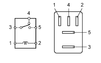
Measure the resistance according to the value(s) in the table below.
Standard resistance Tester Connection Condition Specified Condition 3 - 4 Voltage is not applied between terminals 1 and 2 Below 1 Ω 3 - 4 Apply battery voltage between terminals 1 and 2 10 kΩ or higher 3 - 5 Voltage is not applied between terminals 1 and 2 10 kΩ or higher 3 - 5 Apply battery voltage between terminals 1 and 2 Below 1 Ω If the result is not as specified, replace the No. 2 glass hatch junction relay.
- OKClick here
- NGClick here
-
- Click here
CHECK NO. 1 GLASS HATCH JUNCTION RELAY
-
Measure the resistance according to the value(s) in the table below.
Standard resistance Tester Connection Condition Specified Condition 3 - 4 Voltage is not applied between terminals 1 and 2 Below 1 Ω 3 - 4 Apply battery voltage between terminals 1 and 2 10 kΩ or higher 3 - 5 Voltage is not applied between terminals 1 and 2 10 kΩ or higher 3 - 5 Apply battery voltage between terminals 1 and 2 Below 1 Ω If the result is not as specified, replace the No. 1 glass hatch junction relay.
- OKClick here
- NGClick here
-
- Click here
CHECK HARNESS AND CONNECTOR (MAIN BODY ECU - GLASS HATCH OPENER SWITCH)
-
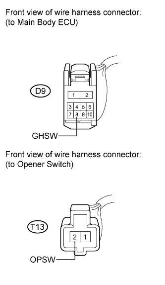
Disconnect the D9 and T13 connectors.
-
Measure the resistance according to the value(s) in the table below.
Standard resistance Tester Connection Condition Specified Condition D9-8 (GHSW) - T13-2 (OPSW) Always Below 1 Ω D9-8 (GHSW) - Body ground Always 10 kΩ or higher
- OKClick here
- NGClick here
-
- Click here
CHECK HARNESS AND CONNECTOR (MAIN BODY ECU - NO. 2 JUNCTION RELAY)
-
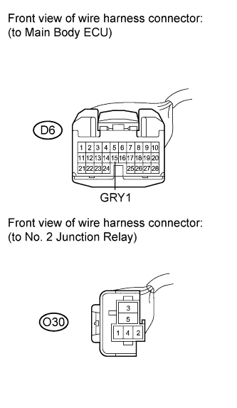
Disconnect the D6 and O30 connectors.
-
Measure the resistance according to the value(s) in the table below.
Standard resistance Tester Connection Condition Specified Condition D6-15 (GRY1) - O30-1 Always Below 1 Ω D6-15 (GRY1) - Body ground Always 10 kΩ or higher
- OKClick here
- NGClick here
-
- Click here
CHECK HARNESS AND CONNECTOR (NO. 2 JUNCTION RELAY - NO. 1 JUNCTION RELAY)
-
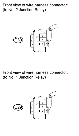
Disconnect the O30 and O29 connectors.
Measure the resistance according to the value(s) in the table below.
Standard resistance Tester Connection Condition Specified Condition O30-3 - O29-2 Always Below 1 Ω O30-3 - Body ground Always 10 kΩ or higher
- OKClick here
- NGClick here
-
- Click here
CHECK HARNESS AND CONNECTOR (NO. 1 JUNCTION RELAY - MAIN BODY ECU)
-
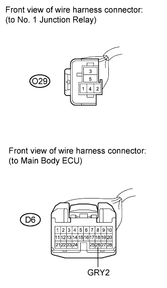
Disconnect the O29 and D6 connectors.
-
Measure the resistance according to the value(s) in the table below.
Standard resistance Tester Connection Condition Specified Condition O29-1 - D6-26 (GRY2) Always Below 1 Ω O29-1 - Body ground Always 10 kΩ or higher
- OKClick here
- NGClick here
-
- Click here
CHECK HARNESS AND CONNECTOR (NO. 1 JUNCTION RELAY - BACK WINDOW LOCK)
-
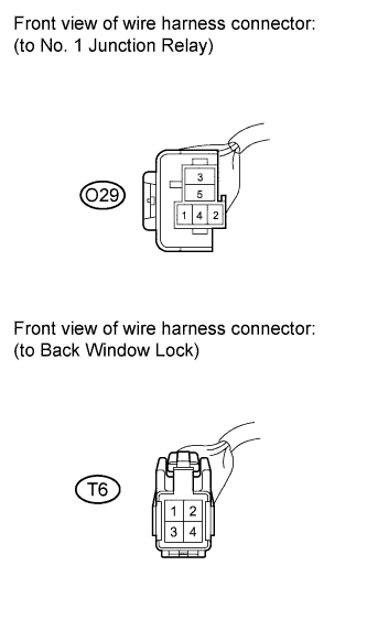
Disconnect the O29 and T6 connectors.
Measure the resistance according to the value(s) in the table below.
Standard resistance Tester Connection Condition Specified Condition O29-3 - T6-3 Always Below 1 Ω O29-3 - Body ground Always 10 kΩ or higher
- OKClick here
- NGClick here
-
- Click here
CHECK HARNESS AND CONNECTOR (MAIN BODY ECU - BACK WINDOW LOCK ASSEMBLY)
-
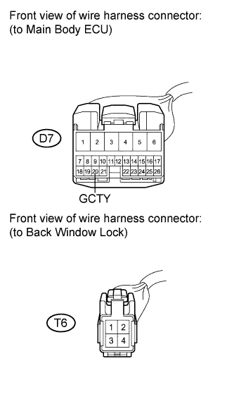
Disconnect the D7 and T6 connectors.
-
Measure the resistance according to the value(s) in the table below.
Standard resistance Tester Connection Condition Specified Condition D7-20 (GCTY) - T6-2 Always Below 1 Ω D7-20 (GCTY) - Body ground Always 10 kΩ or higher
- OKClick here
- NGClick here
-
- Click here
REPLACE MAIN BODY ECU (INSTRUMENT PANEL JUNCTION BLOCK)
- Click here
REPLACE BACK WINDOW LOCK ASSEMBLYClick here
- Click here
REPLACE GLASS HATCH OPENER SWITCH ASSEMBLYClick here
- Click here
REPLACE NO. 2 GLASS HATCH JUNCTION RELAY
- Click here
REPLACE NO. 1 GLASS HATCH JUNCTION RELAY
- Click here
REPAIR OR REPLACE HARNESS OR CONNECTOR
- Click here
REPAIR OR REPLACE HARNESS OR CONNECTOR
- Click here
REPAIR OR REPLACE HARNESS OR CONNECTOR
- Click here
REPAIR OR REPLACE HARNESS OR CONNECTOR
- Click here
REPAIR OR REPLACE HARNESS OR CONNECTOR