GLASS HATCH OPENER SYSTEM TERMINALS OF ECU
-
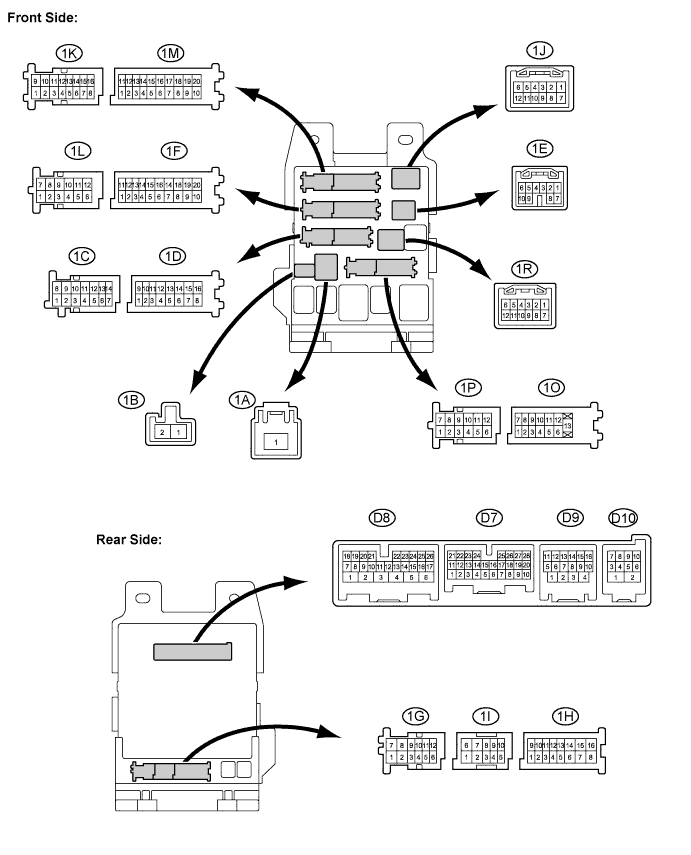
CHECK MAIN BODY ECU
-
Disconnect the 1A, 1D, and 1F junction block connectors.
-
Measure the voltage and resistance between the specified terminals of the wire harness side connectors and body ground.
Standard voltage Tester Connection Wiring Color Terminal Description Condition Specified Condition 1A-1 - Body ground B - Body ground Battery power supply Always 11 to 14 V 1D-16 (ALTB) - Body ground W - Body ground Generator power supply Always 11 to 14 V Standard resistance Tester Connection Wiring Color Terminal Description Condition Specified Condition 1F-10 (GND1) - Body ground W-B - Body ground Ground Always Below 1 Ω 1D-16 (ALTB) - Body ground W - Body ground Ground Always Below 1 Ω If the result is not as specified, there may be a malfunction on the wire harness side.
-
Reconnect the 1A, 1D, and 1F junction block connectors.
-
Measure the voltage according to the value(s) in the table below.
Standard voltage Tester Connection Wiring Color Terminal Description Condition Specified Condition D7-20 (GCTY) - Body ground P - Body ground Glass hatch courtesy switch input Glass hatch is open Below 1 V Glass hatch is closed 11 to 14 V D9-8 (GHSW) - Body ground O - Body ground Glass hatch open signal input Glass hatch is open Below 1 V Glass hatch is closed 11 to 14 V D6-26 (GRY2) - Body ground Y - Body ground NO.1 glass hatch relay signal Ignition switch: on (IG)
Glass hatch open switch: on
Below 1 V Ignition switch: on (IG)
Glass hatch open switch: off
11 to 14 V D6-15 (GRY1) - Body ground V - Body ground NO.2 glass hatch relay signal Ignition switch: on (IG)
Glass hatch open switch: on
Below 1 V Ignition switch: on (IG)
Glass hatch open switch: off
11 to 14 V
-