POWER WINDOW CONTROL SYSTEM Key-off Operation Function Operates even if Operating Conditions are not Satisfied
DESCRIPTION
-
When the driver door has not been opened and fully closed, each door power window regulator motor can control its power window operation for approximately 45 seconds after the ignition switch is turned from on (IG) to off (the key is removed) by receiving operation permission signals from the main body ECU. However, when approximately 45 seconds have elapsed, or the driver door or front passenger side door is opened within approximately 45 seconds of the ignition switch being turned off (the key is removed), the power window regulator motor stops operating.
During AUTO function operation, the window operation will continue until complete even if 45 seconds have passed or a door is opened.
Note
-
The power window control system uses a multiplex communication system (LIN). Inspect the communication function by following HOW TO PROCEED WITH TROUBLESHOOTING. Troubleshoot the power window control system after confirming that the communication system is functioning properly.
-
The power window control system prohibits the AUTO UP/DOWN function when the jam protection function malfunctions. Therefore, troubleshoot the power window control system after confirming that no diagnostic codes are displayed.
-
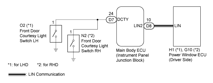
WIRING DIAGRAM
INSPECTION PROCEDURE
Note
When using the intelligent tester to troubleshoot the LIN communication line: Connect the intelligent tester to the vehicle, and turn the courtesy light switch on and off at 1.5 second intervals until communication between the tester and vehicle begins.
PROCEDURE
-
READ VALUE USING INTELLIGENT TESTER (LIN COMMUNICATION)
-
Use the Data List to check the function of the power window regulator master switch.
-
Connect the intelligent tester to the DLC3.
-
Turn the ignition switch on (IG) and turn the tester ON.
-
Select the following menu items: Body / Body ECU / Data List / Comm D-Door Mtr.
-
Read the indication displayed on the tester.
Body ECU: Tester Display Measurement Item/Range Normal Condition Diagnostic Note Communication D-Door Motor Connection status between power window regulator motor assembly (driver side) and main body ECU / OK or Stop OK: Connection
Stop: No connection
- OK OK is displayed on the intelligent tester screen.
-
NG 
GO TO DTC (B2321) Click here
OK 
-
-
CHECK OPERATION FUNCTION AFTER IGNITION SWITCH IS TURNED OFF
-
Check the power window operation function after the ignition switch is turned off.
Result Result Proceed to When power window can still be operated even after opening driver door or front passenger door within approximately 45 seconds of ignition switch being turned off A When power window can still be operated even after approximately 45 seconds have elapsed after ignition switch turned off B
B
REPLACE POWER WINDOW REGULATOR MOTOR ASSEMBLY (for Driver Side) Click here
A
-
-
READ VALUE USING INTELLIGENT TESTER (DOOR COURTESY LIGHT SWITCH)
-
Use the Data List to check the driver side door courtesy switch signal.
-
Connect the intelligent tester to the DLC3.
-
Turn the ignition switch on (IG) and turn the tester on.
-
Select the following menu items: Body / Body ECU / Data List / D Dor Cty SW.
-
Read the indication displayed on the tester.
Body ECU: Tester Display Measurement Item/Range Normal Condition Diagnostic Note D Door Courtesy Switch Driver side door courtesy switch signal / ON or OFF ON: Driver door open
OFF: Driver door closed
- OK OK is displayed on the intelligent tester screen.
-
NG 
INSPECT FRONT DOOR COURTESY LIGHT SWITCH ASSEMBLY Click here
OK 
REPLACE MAIN BODY ECU (INSTRUMENT PANEL JUNCTION BLOCK)
-
-
INSPECT FRONT DOOR COURTESY LIGHT SWITCH ASSEMBLY
-
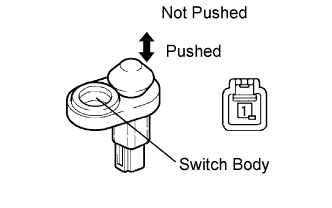
Measure the resistance according to the value(s) in the table below.
Standard resistance Tester Connection Switch Condition Specified Condition 1 - Switch body Pushed 10 kΩ or higher 1 - Switch body Not pushed Below 1 Ω
NG
REPLACE DOOR COURTESY LIGHT SWITCH ASSEMBLY
OK
-
-
CHECK WIRE HARNESS (MAIN BODY ECU - DRIVER SIDE COURTESY SWITCH)
-
Check the harness and connector between the main body ECU and driver side door courtesy switch.
-
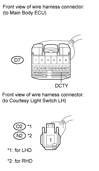
Disconnect the D7 main body ECU connector.
-
Disconnect the O2 switch connector (LHD).
-
Disconnect the N2 switch connector (RHD).
-
Measure the resistance according to the value(s) in the table below.
Standard resistance for LHD Tester Connection Condition Specified Condition D7-24 (DCTY) - O2-1 (Driver side) Always Below 1 Ω D7-24 (DCTY) - Body ground Always 10 kΩ or higher for RHD Tester Connection Condition Specified Condition D7-24 (DCTY) - N2-1 (Driver side) Always Below 1 Ω D7-24 (DCTY) - Body ground Always 10 kΩ or higher
NG
REPAIR OR REPLACE HARNESS OR CONNECTOR
OK
REPLACE MAIN BODY ECU (INSTRUMENT PANEL JUNCTION BLOCK)
-