POWER WINDOW CONTROL SYSTEM Driver Side Power Window Auto Up / Down Function does not Operate with Power Window Master Switch
DESCRIPTION
-
When the AUTO UP/DOWN does not function, the power window control system may be in fail-safe mode. If the system has not been initialized after replacement of the driver door power window regulator motor, it also results in the same problem.
Note
-
The power window control system uses a multiplex communication system (LIN). Inspect the communication function by following HOW TO PROCEED WITH TROUBLESHOOTING. Troubleshoot the power window control system after confirming that the communication system is functioning properly.
-
When the power window regulator motor assembly (on the driver side) is reinstalled or replaced, the power window control system must be initialized.
-
After a door glass or a door glass run has been replaced, the jam protection function may operate unexpectedly when the AUTO UP function is used. In such cases, the AUTO UP function can be resumed by repeating the following operation at least 5 times:
-
Close the power window by fully pulling up the power window switch and holding it in the AUTO UP position.
-
Open the power window by fully pushing down the switch.
Tech Tips
If the pulse sensor built into the power window regulator motor assembly (on the driver side) malfunctions, the power window control system enters fail-safe mode. The remote UP/DOWN and AUTO UP/DOWN functions cannot be operated during fail-safe mode. (However, the power window can be closed by holding the power window switch at the AUTO UP position, and opened manually by pushing down the switch.)
-
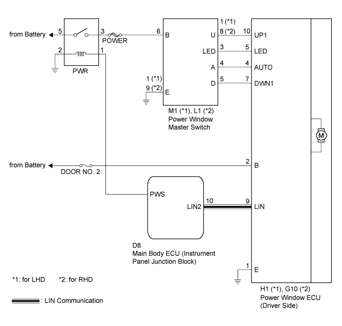
WIRING DIAGRAM
INSPECTION PROCEDURE
PROCEDURE
-
CHECK DTC
-
Check for DTCs.
-
Connect the intelligent tester to the DLC3.
-
By following the tester screen display, check whether any DTCs are output.
Result Result Proceed to No DTCs output A DTCs output B
B 
PROCEED TO INSPECTION PROCEDURE RELEVANT TO OUTPUT DTC
A 
-
-
READ VALUE USING INTELLIGENT TESTER (D-DOOR MOTOR)
-
Use the Data List to check the function of the power window master switch.
D-Door Motor: Tester Display Measurement Item/Range Normal Condition Diagnostic Note D P/W Auto Switch Driver side power window AUTO switch signal / ON or OFF ON: Driver side power window AUTO switch operates
OFF: Driver side power window AUTO switch does not operate
- D P/W Up Switch Driver side power window UP switch signal / ON or OFF ON: Driver side power window UP switch operates
OFF: Driver side power window UP switch does not operate
- D P/W Down Switch Driver side power window DOWN switch signal / ON or OFF ON: Driver side power window DOWN switch operates
OFF: Driver side power window DOWN switch does not operate
- OK ON (switch operates) appears on screen.
NG 
INSPECT POWER WINDOW MASTER SWITCH Click here
OK 
REPLACE POWER WINDOW REGULATOR MOTOR ASSEMBLY (for Driver Side) Click here
-
-
INSPECT POWER WINDOW MASTER SWITCH
-
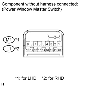
Measure the resistance according to the value(s) in the table below.
Standard resistance for LHD Tester Connection Condition Specified Condition 8 (U) - 1 (E) - 4 (A) Auto UP Below 1 Ω 4 (A) - 5 (D) - 1 (E) Auto Down Below 1 Ω for RHD Tester Connection Condition Specified Condition 1 (U) - 9 (E) - 4 (A) Auto UP Below 1 Ω 4 (A) - 5 (D) - 9 (E) Auto Down Below 1 Ω
NG
REPLACE POWER WINDOW MASTER SWITCH Click here
OK
-
-
INSPECT FUSE (DOOR NO. 2)
-
Remove the DOOR NO. 2 fuse from the instrument panel junction block.
-
Measure the resistance according to the value(s) in the table below.
Standard resistance Tester Connection Condition Specified Condition DOOR NO. 2 Always Below 1 Ω
NG
REPLACE FUSE (DOOR NO. 2)
OK
-
-
CHECK WIRE HARNESS (MASTER SWITCH - REGULATOR MOTOR)
-
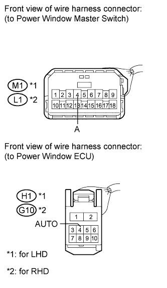
Disconnect the M1 and H1 connectors (LHD).
-
Disconnect the L1 and G10 connectors (RHD).
-
Measure the resistance according to the value(s) in the table below.
Standard resistance for LHD Tester Connection Condition Specified Condition M1-4 (A) - H1-4 (AUTO) Always Below 1 Ω for RHD Tester Connection Condition Specified Condition L1-4 (A) - G10-4 (AUTO) Always Below 1 Ω
NG
REPAIR OR REPLACE HARNESS OR CONNECTOR
OK
REPLACE POWER WINDOW REGULATOR MOTOR ASSEMBLY (for Driver Side) Click here
-