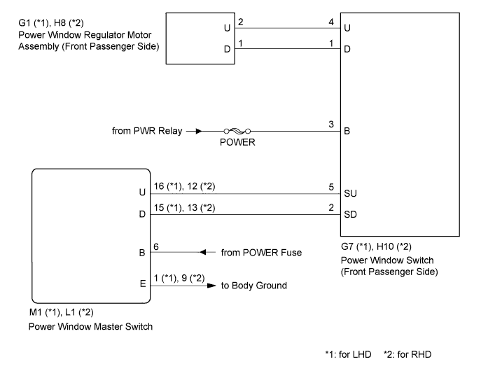
POWER WINDOW CONTROL SYSTEM Front Passenger Side Power Window does not Operate with Front Passenger Side Power Window Switch
DESCRIPTION
If the passenger side manual UP/DOWN function does not operate, a malfunction may exist in the power window regulator motor, power window switch, power window master switch or wire harness.
WIRING DIAGRAM
INSPECTION PROCEDURE
PROCEDURE
-
CHECK POWER WINDOW SWITCH (FRONT PASSENGER SIDE) (POWER SOURCE)
-
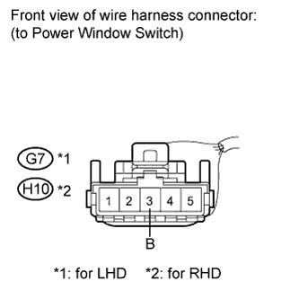
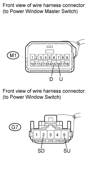
Disconnect the G7 connector (LHD).
-
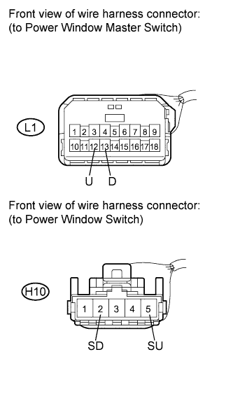
Disconnect the H10 connector (RHD).
-
Measure the voltage according to the value(s) in the table below.
Standard voltage for LHD Tester Connection Condition Specified Condition G7-3 (B) - Body ground Ignition switch on (IG) 11 to 14 V for RHD Tester Connection Condition Specified Condition H10-3 (B) - Body ground Ignition switch on (IG) 11 to 14 V
NG 
REPAIR OR REPLACE HARNESS OR CONNECTOR
OK 
-
-
INSPECT POWER WINDOW SWITCH (FRONT PASSENGER SIDE)
-
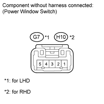
Measure the resistance when the switch is operated according to the value(s) in the table below.
Standard resistance Tester Connection Switch Condition Specified Condition 1 (D) - 2 (SD) UP Below 1 Ω 3 (B) - 4 (U) Below 1 Ω 1 (D) - 2 (SD) OFF Below 1 Ω 4 (U) - 5 (SU) Below 1 Ω 4 (U) - 5 (SU) DOWN Below 1 Ω 1 (D) - 3 (B) Below 1 Ω
NG
REPLACE POWER WINDOW SWITCH (FRONT PASSENGER SIDE) Click here
OK
-
-
CHECK HARNESS AND CONNECTOR (SWITCH (FRONT PASSENGER SIDE) - MOTOR (FRONT PASSENGER SIDE))
-
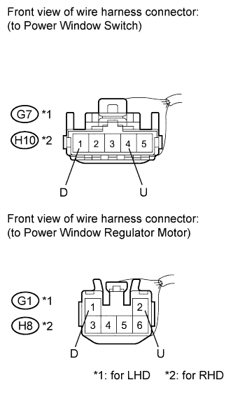
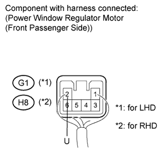
Disconnect the G7 and G1 connectors (LHD).
-
Disconnect the H10 and H8 connectors (RHD).
-
Measure the resistance according to the value(s) in the table below.
Standard resistance for LHD Tester Connection Condition Specified Condition G7-4 (U) - G1-2 (U) Always Below 1 Ω G7-1 (D) - G1-1 (D) Always Below 1 Ω G7-4 (U) - Body ground Always 10 kΩ or higher G7-1 (D) - Body ground Always 10 kΩ or higher for RHD Tester Connection Condition Specified Condition H10-4 (U) - H8-2 (U) Always Below 1 Ω H10-1 (D) - H8-1 (D) Always Below 1 Ω H10-4 (U) - Body ground Always 10 kΩ or higher H10-1 (D) - Body ground Always 10 kΩ or higher
NG
REPAIR OR REPLACE HARNESS OR CONNECTOR
OK
-
-
INSPECT POWER WINDOW REGULATOR MOTOR ASSEMBLY (FRONT PASSENGER SIDE)
-
Check power window regulator motor operation.
-
Remove the power window regulator motor Click here.
-
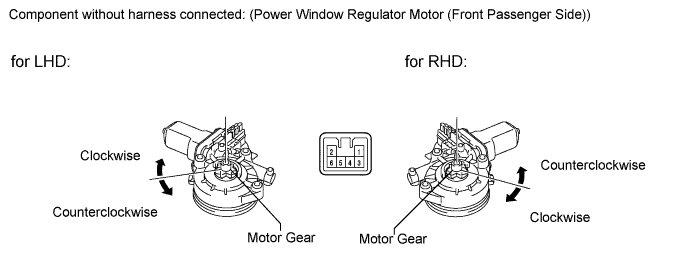
Apply battery voltage to the motor connector according to the table below.
Note
Do not apply battery voltage to any terminals except terminals 1 and 2.
OK Measurement Condition Specified Condition Battery negative (-) → Terminal 2
Battery positive (+) → Terminal 1
Motor gear rotates clockwise Battery negative (-) → Terminal 1
Battery positive (+) → Terminal 2
Motor gear rotates counterclockwise
-
-
Check PTC operation:
Note
The work must be performed with the power window regulator and door glass installed on the vehicle.
-
Install the power window regulator motor Click here.
-
Connect an electrical tester DC 400 A probe to the wire harness of terminal 2.
Note
Match the arrow mark of the probe with the direction of the current flow.
-
Fully close the door glass by pressing the power window UP switch. Wait for approximately 60 seconds.
-
Continue to press the power window UP switch and measure how long it takes for the electrical current to change from a range of 16 to 28 A to approximately 1 A (Inspection of current shut-off).
Standard 4 to 90 seconds -
60 seconds after the previous step, press the power window DOWN switch (passenger side).
OK The passenger side window goes down.
-
NG
REPLACE POWER WINDOW REGULATOR MOTOR ASSEMBLY (FRONT PASSENGER SIDE) Click here
OK
-
-
CHECK HARNESS AND CONNECTOR (MASTER SWITCH - SWITCH (FRONT PASSENGER SIDE))
-
for LHD:
-
Front passenger side:
Disconnect the M1 and G7 connectors.
-
Measure the resistance according to the value(s) in the table below.
Standard resistance Tester Connection Condition Specified Condition M1-16 (U) - G7-5 (SU) Always Below 1 Ω M1-15 (D) - G7-2 (SD) Always Below 1 Ω M1-16 (U) - Body ground Always 10 kΩ or higher M1-15 (D) - Body ground Always 10 kΩ or higher
-
-
for RHD:
-
Front passenger side:
Disconnect the L1 and H10 connectors.
-
Measure the resistance according to the value(s) in the table below.
Standard resistance Tester Connection Condition Specified Condition L1-12 (U) - H10-5 (SU) Always Below 1 Ω L1-13 (D) - H10-2 (SD) Always Below 1 Ω L1-12 (U) - Body ground Always 10 kΩ or higher L1-13 (D) - Body ground Always 10 kΩ or higher
-
NG
REPAIR OR REPLACE HARNESS OR CONNECTOR
OK 
REPLACE POWER WINDOW MASTER SWITCH Click here
-