POWER WINDOW CONTROL SYSTEM Driver Side Power Window does not Operate with Power Window Master Switch
DESCRIPTION
If the manual UP/DOWN and AUTO DOWN functions do not operate, a malfunction may exist in the power window master switch, power window regulator motor or wire harness.
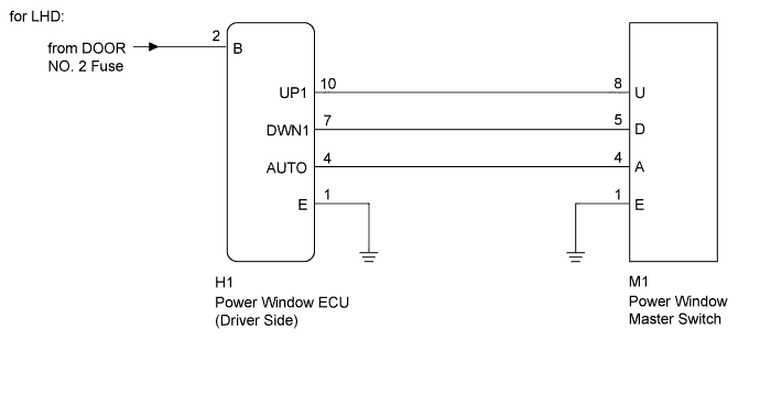
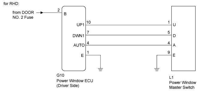
WIRING DIAGRAM
INSPECTION PROCEDURE
PROCEDURE
-
INSPECT POWER WINDOW MASTER SWITCH (DRIVER SWITCH)
-
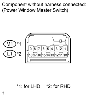
Measure the resistance according to the value(s) in the table below.
Standard resistance for LHD Tester Connection Condition Specified Condition 8 (U) - 1 (E) - 4 (A) Auto UP Below 1 Ω 8 (U) - 1 (E) Manual UP Below 1 Ω 5 (D) - 1 (E) Manual DOWN Below 1 Ω 4 (A) - 5 (D) - 1 (E) Auto DOWN Below 1 Ω for RHD Tester Connection Condition Specified Condition 1 (U) - 9 (E) - 4 (A) Auto UP Below 1 Ω 1 (U) - 9 (E) Manual UP Below 1 Ω 5 (D) - 9 (E) Manual DOWN Below 1 Ω 4 (A) - 5 (D) - 9 (E) Auto DOWN Below 1 Ω
NG 
REPLACE POWER WINDOW MASTER SWITCH Click here
OK 
-
-
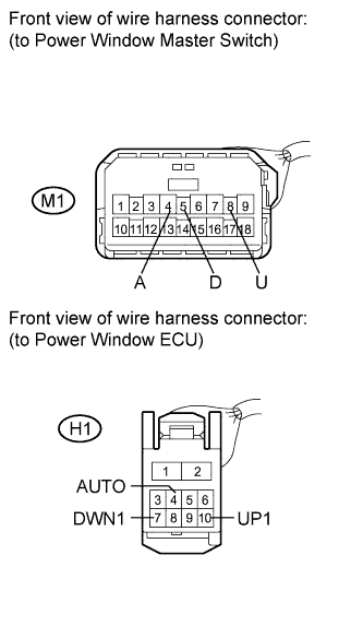
CHECK HARNESS AND CONNECTOR (MASTER SWITCH - MOTOR (DRIVER SIDE))
-
for LHD:
-
Disconnect the M1 and H1 connectors.
-
Measure the resistance according to the value(s) in the table below.
Standard resistance Tester Connection Condition Specified Condition M1-8 (U) - H1-10 (UP1) Always Below 1 Ω M1-4 (A) - H1-4 (AUTO) Always Below 1 Ω M1-5 (D) - H1-7 (DWN1) Always Below 1 Ω M1-8 (U) - Body ground Always 10 kΩ or higher M1-4 (A) - Body ground Always 10 kΩ or higher M1-5 (D) - Body ground Always 10 kΩ or higher
-
-
for RHD:
-
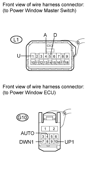
Disconnect the L1 and G10 connectors.
-
Measure the resistance according to the value(s) in the table below.
Standard resistance Tester Connection Condition Specified Condition L1-1 (U) - G10-10 (UP1) Always Below 1 Ω L1-4 (A) - G10-4 (AUTO) Always Below 1 Ω L1-5 (D) - G10-7 (DWN1) Always Below 1 Ω L1-1 (U) - Body ground Always 10 kΩ or higher L1-4 (A) - Body ground Always 10 kΩ or higher L1-5 (D) - Body ground Always 10 kΩ or higher
-
NG
REPAIR OR REPLACE HARNESS OR CONNECTOR
OK
-
-
INSPECT POWER WINDOW REGULATOR MOTOR ASSEMBLY (DRIVER SIDE)
-
Remove the power window regulator motor assembly Click here.
-
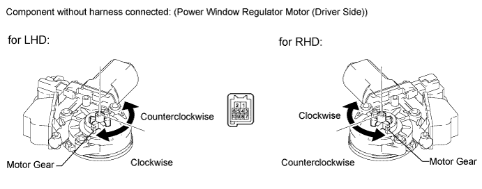
Apply battery voltage to the motor connector according to the table below.
Note
Do not apply battery voltage to any terminals except terminals 1, 2, 4, 7, 9 and 10.
OK Switch Condition Measurement Condition Specified Condition Manual Operation Battery positive (+) → Terminal 2 (B), 9 (LIN)
Battery negative (-) → Terminal 1 (E), 7 (DWN1)
Motor gear rotates counterclockwise Battery positive (+) → Terminal 2 (B), 9 (LIN)
Battery negative (-) → Terminal 1 (E), 10 (UP1)
Motor gear rotates clockwise Auto Operation Battery positive (+) → Terminal 2 (B), 9 (LIN)
Battery negative (-) → Terminal 1 (E), 4 (AUTO), 7 (DWN1)
Motor gear rotates counterclockwise Battery positive (+) → Terminal 2 (B), 9 (LIN)
Battery negative (-) → Terminal 1 (E), 4 (AUTO), 10 (UP1)
Motor gear rotates clockwise
-
NG
REPLACE POWER WINDOW REGULATOR MOTOR ASSEMBLY (for Driver Side) Click here
OK 
REPLACE POWER WINDOW MASTER SWITCH Click here
-