POWER WINDOW CONTROL SYSTEM Remote Up / Down Function does not Operate
DESCRIPTION
With the ignition switch ON, the power window regulator master switch transmits remote switch signals to the regulator switch of the passenger door power window. Then, the regulator switch drives the passenger power window regulator motor.
WIRING DIAGRAM
INSPECTION PROCEDURE
PROCEDURE
-
CHECK POWER WINDOW REGULATOR MASTER SWITCH ASSEMBLY
-
Turn the window lock switch OFF and operate the switches on the master switch. Check that the remote UP / DOWN function operates normally.
OK Remote UP / DOWN function operates normally.
NG 
CHECK MANUAL UP / DOWN FUNCTION Click here
OK 
END
-
-
CHECK MANUAL UP / DOWN FUNCTION
-
Check that the passenger door power window manual UP / DOWN function operates normally.
OK Manual UP / DOWN function operates normally.
NG
HARNESS AND CONNECTOR (POWER WINDOW MASTER SWITCH - BATTERY AND BODY GROUND) Click here
OK
REPLACE POWER WINDOW MASTER SWITCH Click here
-
-
HARNESS AND CONNECTOR (POWER WINDOW MASTER SWITCH - BATTERY AND BODY GROUND)
-
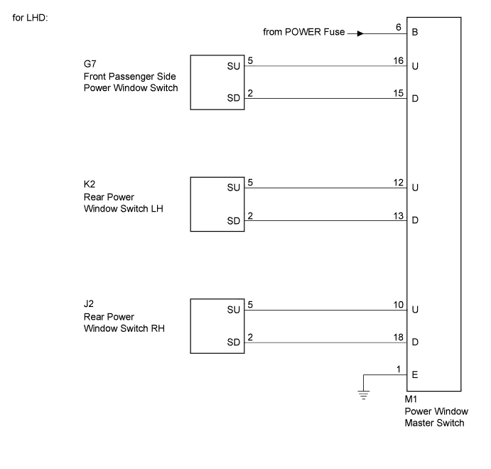
for LHD:
-
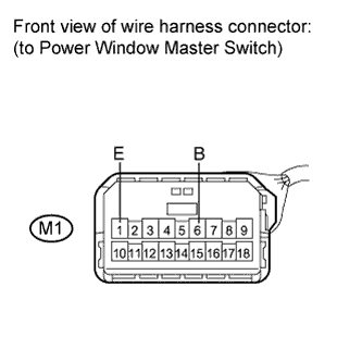
Disconnect the M1 connector.
-
Measure the voltage and resistance according to the value(s) in the table below.
Standard voltage Tester Connection Condition Specified Condition M1-6 (B) - Body ground Ignition switch on (IG) 11 to 14 V Standard resistance Tester Connection Condition Specified Condition M1-1 (E) - Body ground Always Below 1 Ω
-
-
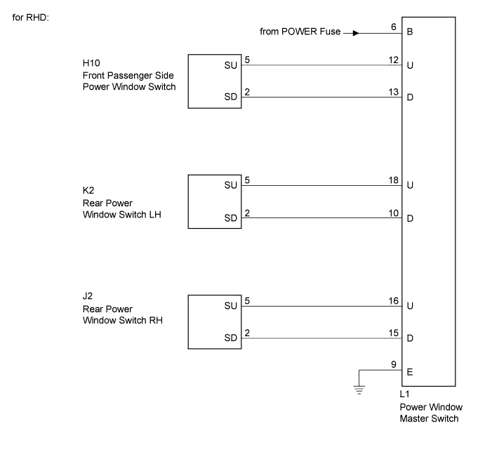
for RHD:
-
Disconnect the L1 connector.
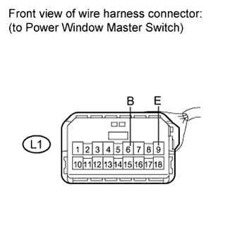
-
Measure the voltage and resistance according to the value(s) in the table below.
Standard voltage Tester Connection Condition Specified Condition L1-6 (B) - Body ground Ignition switch on (IG) 11 to 14 V Standard resistance Tester Connection Condition Specified Condition L1-9 (E) - Body ground Always Below 1 Ω
-
NG 
REPAIR OR REPLACE HARNESS OR CONNECTOR
OK 
-
-
INSPECT POWER WINDOW MASTER SWITCH
-
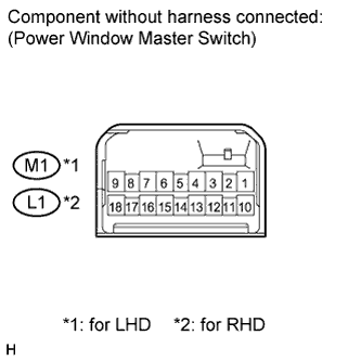
Measure the resistance according to the value(s) in the table below.
Standard resistance for LHD Tester Connection Condition Specified Condition 6 (B) - 16 (U)
15 (D) - 1 (E)
UP (Passenger side) Below 1 Ω 6 (B) - 15 (D)
16 (U) - 1 (E)
DOWN (Passenger side) Below 1 Ω 6 (B) - 12 (U)
13 (D) - 1 (E)
UP (Rear LH) Below 1 Ω 6 (B) - 13 (D)
12 (U) - 1 (E)
DOWN (Rear LH) Below 1 Ω 6 (B) - 10 (U)
18 (D) - 1 (E)
UP (Rear RH) Below 1 Ω 6 (B) - 18 (D)
10 (U) - 1 (E)
DOWN (Rear RH) Below 1 Ω for RHD Tester Connection Condition Specified Condition 6 (B) - 12 (U)
13 (D) - 9 (E)
UP (Passenger side) Below 1 Ω 6 (B) - 13 (D)
12 (U) - 9 (E)
DOWN (Passenger side) Below 1 Ω 6 (B) - 18 (U)
10 (D) - 9 (E)
UP (Rear LH) Below 1 Ω 6 (B) - 10 (D)
18 (U) - 9 (E)
DOWN (Rear LH) Below 1 Ω 6 (B) - 16 (U)
15 (D) - 9 (E)
UP (Rear RH) Below 1 Ω 6 (B) - 15 (D)
16 (U) - 9 (E)
DOWN (Rear RH) Below 1 Ω
NG
REPLACE POWER WINDOW MASTER SWITCH Click here
OK
-
-
CHECK HARNESS AND CONNECTOR (MASTER SWITCH - FRONT PASSENGER, REAR LH/RH SWITCH)
-
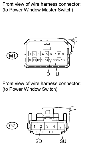
for LHD:
-
Front passenger side:
Disconnect the M1 and G7 connectors.
-
Measure the resistance according to the value(s) in the table below.
Standard resistance Tester Connection Condition Specified Condition M1-16 (U) - G7-5 (SU) Always Below 1 Ω M1-15 (D) - G7-2 (SD) Always Below 1 Ω M1-16 (U) - Body ground Always 10 kΩ or higher M1-15 (D) - Body ground Always 10 kΩ or higher -
for Rear LH side:
Disconnect the M1 and K2 connectors.
-
Measure the resistance according to the value(s) in the table below.
Standard resistance Tester Connection Condition Specified Condition M1-12 (U) - K2-5 (SU) Always Below 1 Ω M1-13 (D) - K2-2 (SD) Always Below 1 Ω M1-12 (U) - Body ground Always 10 kΩ or higher M1-13 (D) - Body ground Always 10 kΩ or higher -
for Rear RH side:
Disconnect the M1 and J2 connectors.
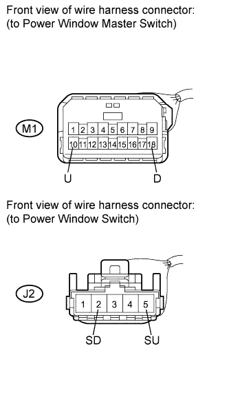
-
Measure the resistance according to the value(s) in the table below.
Standard resistance Tester Connection Condition Specified Condition M1-10 (U) - J2-5 (SU) Always Below 1 Ω M1-18 (D) - J2-2 (SD) Always Below 1 Ω M1-10 (U) - Body ground Always 10 kΩ or higher M1-18 (D) - Body ground Always 10 kΩ or higher
-
-
for RHD:
-
Front passenger side:
Disconnect the L1 and H10 connectors.
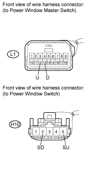
-
Measure the resistance according to the value(s) in the table below.
Standard resistance Tester Connection Condition Specified Condition L1-12 (U) - H10-5 (SU) Always Below 1 Ω L1-13 (D) - H10-2 (SD) Always Below 1 Ω L1-12 (U) - Body ground Always 10 kΩ or higher L1-13 (D) - Body ground Always 10 kΩ or higher -
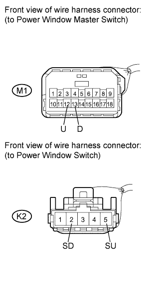
for Rear LH side:
Disconnect the L1 and K2 connectors.
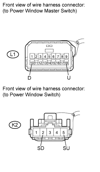
-
Measure the resistance according to the value(s) in the table below.
Standard resistance Tester Connection Condition Specified Condition L1-18 (U) - K2-5 (SU) Always Below 1 Ω L1-10 (D) - K2-2 (SD) Always Below 1 Ω L1-18 (U) - Body ground Always 10 kΩ or higher L1-10 (D) - Body ground Always 10 kΩ or higher -
for Rear RH side:
Disconnect the L1 and J2 connectors.
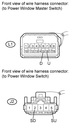
-
Measure the resistance according to the value(s) in the table below.
Standard resistance Tester Connection Condition Specified Condition L1-16 (U) - J2-5 (SU) Always Below 1 Ω L1-15 (D) - J2-2 (SD) Always Below 1 Ω L1-16 (U) - Body ground Always 10 kΩ or higher L1-15 (D) - Body ground Always 10 kΩ or higher
-
NG
REPAIR OR REPLACE HARNESS OR CONNECTOR
OK
REPLACE POWER WINDOW SWITCH (APPLICABLE LOCATION)
-