POWER WINDOW CONTROL SYSTEM, Diagnostic DTC:B2312
| DTC Code | DTC Name |
|---|---|
| B2312 | Driver Side Door Master Switch Malfunction |
DESCRIPTION
The portion of the power window control system that is located in the driver door consists of a power window master switch, regulator, and a motor with an integrated ECU. The driver door power window regulator motor is controlled by the ECU when the power window master switch is operated (models with jam protection).
When the ECU determines that the power window master switch is stuck, DTC B2312 is set.
Note
The power window control system uses a serial communication protocol (LIN) to communicate with the main body ECU. Inspect the communication function by following HOW TO PROCEED WITH TROUBLESHOOTING. Troubleshoot the power window control system after confirming that the communication system is functioning properly.
| DTC Code | DTC Detection Condition | Trouble Area |
|---|---|---|
| B2312 | The power window regulator master switch is stuck |
|
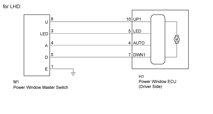
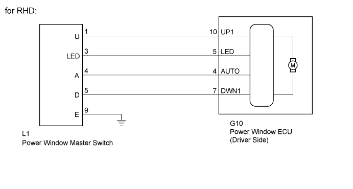
WIRING DIAGRAM
INSPECTION PROCEDURE
PROCEDURE
-
CHECK DTC OUTPUT
-
Turn the ignition switch off.
-
Wait for at least 10 seconds, and then turn the ignition switch on (IG).
-
Check whether the DTC output recurs.
Result Result Proceed to B2312 A No output B
B 
END (DUE TO KEEPING SWITCH OPERATED FOR 20 SECONDS OR MORE)
A 
-
-
INSPECT POWER WINDOW MASTER SWITCH
-
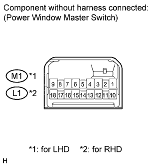
Measure the resistance according to the value(s) in the table below.
Standard resistance for LHD Tester Connection Condition Specified Condition 8 (U) - 1 (E) - 4 (A) Auto UP Below 1 Ω 8 (U) - 1 (E) Manual UP Below 1 Ω 5 (D) - 1 (E) Manual DOWN Below 1 Ω 4 (A) - 5 (D) - 1 (E) Auto DOWN Below 1 Ω for RHD Tester Connection Condition Specified Condition 1 (U) - 9 (E) - 4 (A) Auto UP Below 1 Ω 1 (U) - 9 (E) Manual UP Below 1 Ω 5 (D) - 9 (E) Manual DOWN Below 1 Ω 4 (A) - 5 (D) - 9 (E) Auto DOWN Below 1 Ω
NG
REPLACE POWER WINDOW MASTER SWITCH Click here
OK
-
-
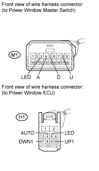
CHECK HARNESS AND CONNECTOR (POWER WINDOW MASTER SWITCH - WINDOW REGULATOR MOTOR)
-
for LHD:
-
Disconnect the M1 and H1 connectors.
-
Measure the resistance according to the value(s) in the table below.
Standard resistance Tester Connection Condition Specified Condition M1-8 (U) - H1-10 (UP1) Always Below 1 Ω M1-3 (LED) - H1-5 (LED) Always Below 1 Ω M1-4 (A) - H1-4 (AUTO) Always Below 1 Ω M1-5 (D) - H1-7 (DWN1) Always Below 1 Ω M1-8 (U) - Body ground Always 10 kΩ or higher M1-3 (LED) - Body ground Always 10 kΩ or higher M1-4 (A) - Body ground Always 10 kΩ or higher M1-5 (D) - Body ground Always 10 kΩ or higher
-
-
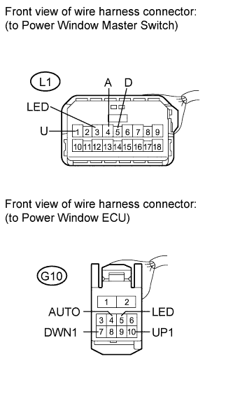
for RHD:
-
Disconnect the L1 and G10 connectors.
-
Measure the resistance according to the value(s) in the table below.
Standard resistance Tester Connection Condition Specified Condition L1-1 (U) - G10-10 (UP1) Always Below 1 Ω L1-3 (LED) - G10-5 (LED) Always Below 1 Ω L1-4 (A) - G10-4 (AUTO) Always Below 1 Ω L1-5 (D) - G10-7 (DWN1) Always Below 1 Ω L1-1 (U) - Body ground Always 10 kΩ or higher L1-3 (LED) - Body ground Always 10 kΩ or higher L1-4 (A) - Body ground Always 10 kΩ or higher L1-5 (D) - Body ground Always 10 kΩ or higher
-
NG
REPAIR OR REPLACE HARNESS OR CONNECTOR
OK 
REPLACE POWER WINDOW REGULATOR MOTOR ASSEMBLY (for Driver Side) Click here
-