- Click here
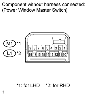
INSPECT POWER WINDOW REGULATOR MASTER SWITCH ASSEMBLY
-
Check that the switch function.
-
Measure the resistance according to the value(s) in the table below.
Standard resistance for LHD Tester Connection Condition Specified Condition 8 (U) - 1 (E) - 4 (A) Auto UP (Driver side) Below 1 Ω 8 (U) - 1 (E) Manual UP (Driver side) Below 1 Ω 5 (D) - 1 (E) Manual DOWN (Driver side) Below 1 Ω 4 (A) - 5 (D) - 1 (E) Auto DOWN (Driver side) Below 1 Ω 6 (B) - 16 (U)
15 (D) - 1 (E)
UP (Passenger side) Below 1 Ω 6 (B) - 15 (D)
16 (U) - 1 (E)
DOWN (Passenger side) Below 1 Ω 6 (B) - 12 (U)
13 (D) - 1 (E)
UP (Rear LH) Below 1 Ω 6 (B) - 13 (D)
12 (U) - 1 (E)
DOWN (Rear LH) Below 1 Ω 6 (B) - 10 (U)
18 (D) - 1 (E)
UP (Rear RH) Below 1 Ω 6 (B) - 18 (D)
10 (U) - 1 (E)
DOWN (Rear RH) Below 1 Ω for RHD Tester Connection Condition Specified Condition 1 (U) - 9 (E) - 4 (A) Auto UP (Driver side) Below 1 Ω 1 (U) - 9 (E) Manual UP (Driver side) Below 1 Ω 5 (D) - 9 (E) Manual DOWN (Driver side) Below 1 Ω 4 (A) - 5 (D) - 9 (E) Auto DOWN (Driver side) Below 1 Ω 6 (B) - 12 (U)
13 (D) - 9 (E)
UP (Passenger side) Below 1 Ω 6 (B) - 13 (D)
12 (U) - 9 (E)
DOWN (Passenger side) Below 1 Ω 6 (B) - 18 (U)
10 (D) - 9 (E)
UP (Rear LH) Below 1 Ω 6 (B) - 10 (D)
18 (U) - 9 (E)
DOWN (Rear LH) Below 1 Ω 6 (B) - 16 (U)
15 (D) - 9 (E)
UP (Rear RH) Below 1 Ω 6 (B) - 15 (D)
16 (U) - 9 (E)
DOWN (Rear RH) Below 1 Ω If the result is not as specified, replace the master switch.
-
-
Check that the LED illuminates.
-
Apply battery voltage to the master switch and check that the LED illuminates.
OK for LHD Measurement Condition Specified Condition Battery positive (+) → Terminal 3 (LED)
Battery negative (-) → Terminal 1 (E)
LED illuminates for RHD Measurement Condition Specified Condition Battery positive (+) → Terminal 3 (LED)
Battery negative (-) → Terminal 9 (E)
LED illuminates If the result is not as specified, replace the master switch.
-
-