CLOCK SYSTEM Illumination Circuit
DESCRIPTION
-
w/o Multi-information Display:
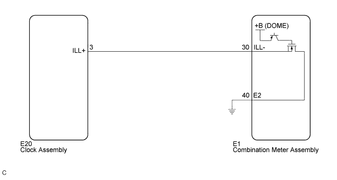
The clock assembly uses this circuit to receive the illumination signal via the direct line. The combination meter assembly controls illumination through the ILL+ terminal.
-
w/ Multi-information Display:
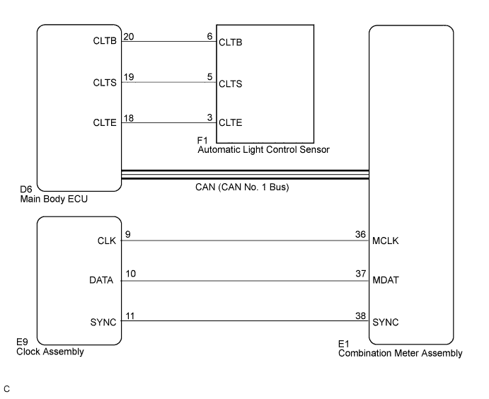
The clock assembly uses this circuit to receive the auto dimmer signal and tail cancel signal. When the clock assembly receives an auto dimmer signal from the main body ECU through the combination meter assembly via the direct line, the combination meter assembly causes the clock display to be dimmed. When the meter CPU receives an auto dimmer signal, it dims the meter illumination and clock illumination. The main body ECU determines whether it is daytime, twilight, or nighttime based on the waveform transmitted from the automatic light control sensor. If the main body ECU determines that it is daytime, the ECU does not send auto dimmer signals. Therefore, the clock illumination (multi-information display) will not dim even if the driver accidentally turns the light control switch to the TAIL or HEAD position in daytime.
Tech Tips
If the automatic light control sensor has a malfunction, DTC B1244 is output. Click here
WIRING DIAGRAM
-
w/o Multi-information Display:
-
w/ Multi-information Display:
INSPECTION PROCEDURE
PROCEDURE
-
CONFIRM SYMPTOMS
-
Confirm the symptom.
Result Result Proceed to Only clock illumination has a malfunction. A Clock illumination, combination meter assembly illumination, and heater control panel illumination have a malfunction. B
B 
GO TO METER / GAUGE SYSTEM Click here
A 
-
-
SYSTEM CHECK
-
Confirm the vehicle model.
Result Result Proceed to w/o Multi-information Display A w/ Multi-information Display B
B 
CHECK CAN COMMUNICATION SYSTEM Click here
A
-
-
CHECK HARNESS AND CONNECTOR (CLOCK ASSEMBLY - COMBINATION METER)
-
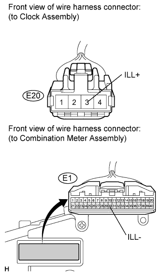
Disconnect E1 and E20 connectors.
-
Measure the resistance according to the value(s) in the table below.
Standard resistance Tester Connection Condition Specified Condition E20-3 (ILL+) - E1-30 (ILL-) Always Below 1 Ω E1-30 (ILL-) - Body ground Always 10 kΩ or higher
NG
REPAIR OR REPLACE HARNESS OR CONNECTOR
OK
-
-
INSPECT CLOCK ASSEMBLY
-
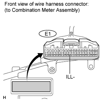
Reconnect the E20 connector.
-
Measure the voltage according to the value(s) in the table below.
Standard voltage Tester Connection Condition Specified Condition E1-30 (ILL-) - Body ground Ignition switch on (IG), headlight dimmer switch TAIL or HEAD 11 to 14 V E1-30 (ILL-) - Body ground Ignition switch on (IG), headlight dimmer switch OFF Below 1 V
NG
REPLACE CLOCK ASSEMBLY Click here
OK 
REPLACE COMBINATION METER ASSEMBLY Click here
-
-
CHECK CAN COMMUNICATION SYSTEM
-
Check if any DTC is output Click here.
Result Result Proceed to CAN communication DTC is not output. A CAN Communication DTC is output. B
B
GO TO CAN COMMUNICATION SYSTEM Click here
A
-
-
PERFORM ACTIVE TEST USING INTELLIGENT TESTER
-
Connect the intelligent tester to the DLC3.
-
Ignition switch on (IG).
-
Turn the tester ON.
-
Enter the following menus: Body Electrical / Main Body / Active Test.
-
Check the clock illumination.
Main Body Tester Display Test Part Control Range Diagnostic Note Dimmer Signal Dimmer Signal Dimmer signal is OFF/ON Confirm that the vehicle is stopped, engine idling OK The clock illumination is dimmed when the Dimmer signal is ON. Tech Tips
Refer to the sensitivity setting in the customization table of the lighting system Click here.
NG
CHECK HARNESS AND CONNECTOR (CLOCK ASSEMBLY - COMBINATION METER) Click here
OK
GO TO LIGHTING SYSTEM Click here
-
-
CHECK HARNESS AND CONNECTOR (CLOCK ASSEMBLY - COMBINATION METER)
-
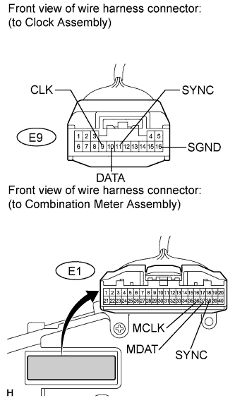
Disconnect the E1 and E9 connectors.
-
Measure the resistance according to the value(s) in the table below.
Standard resistance Tester Connection Condition Specified Condition E9-9 (CLK) - E1-36 (MCLK) Always Below 1 Ω E9-10 (DATA) - E1-37 (MDAT) Always Below 1 Ω E9-11 (SYNC) - E1-38 (SYNC) Always Below 1 Ω E1-36 (MCLK) - Body ground Always 10 kΩ or higher E1-37 (MDAT) - Body ground Always 10 kΩ or higher E1-38 (SYNC) - Body ground Always 10 kΩ or higher
NG
REPAIR OR REPLACE HARNESS OR CONNECTOR
OK
-
-
INSPECT COMBINATION METER ASSEMBLY
-
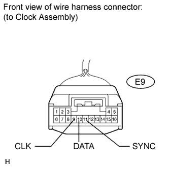
Reconnect the E1 connector.
-
Measure the voltage according to the value(s) in the table below.
Standard voltage Tester Connection Condition Specified Condition E9-9 (CLK) - Body ground Ignition switch on (IG), headlight dimmer switch TAIL or HEAD Pulse generation E9-10 (DATA) - Body ground Ignition switch on (IG), headlight dimmer switch TAIL or HEAD Pulse generation E9-11 (SYNC) - Body ground Ignition switch on (IG), headlight dimmer switch TAIL or HEAD Pulse generation E9-9 (CLK) - Body ground Ignition switch on (IG), headlight dimmer switch OFF Below 1 V E9-10 (DATA) - Body ground Ignition switch on (IG), headlight dimmer switch OFF Below 1 V E9-11 (SYNC) - Body ground Ignition switch on (IG), headlight dimmer switch OFF Below 1 V
NG
REPLACE COMBINATION METER ASSEMBLY Click here
OK
REPLACE CLOCK ASSEMBLY Click here
-