- Click here
INSPECT CLOCK ASSEMBLY (w/o Multi-information Display)
-
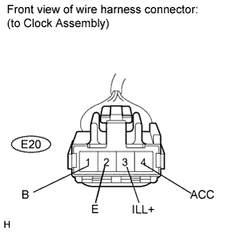
Disconnect the E20 connector.
-
Measure the voltage according to the value(s) in the table below.
Standard voltage Tester Connection Condition Specified Condition E20-1 (B) - Body ground Always 11 to 14 V E20-3 (ILL+) - Body ground Ignition switch on (IG), light control switch OFF Below 1 V Ignition switch on (IG), light control switch TAIL/HEAD 11 to 14 V E20-4 (ACC) - Body ground Ignition switch off Below 1 V Ignition switch on (ACC) 11 to 14 V
-
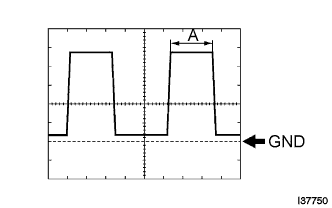
Waveform (Reference): Using oscilloscope:
Item Condition Tool setting 2 V/DIV., 1 ms./DIV. Vehicle condition Ignition switch on (IG), light control switch TAIL/HEAD Tip:
-
Duty ratio changes as the illumination becomes darker (the period "A" shown in the illustration becomes longer).
-
If the value is not as specified, repair or replace the wire harness or connector.
-
-
-
Measure the resistance according to the value(s) in the table below.
Standard resistance Tester Connection Condition Specified Condition E20-2 (E) - Body ground Always Below 1 Ω Tip:If the value is not as specified, repair or replace the wire harness or connector.
-
- Click here
INSPECT CLOCK ASSEMBLY (w/ Multi-information Display)
-
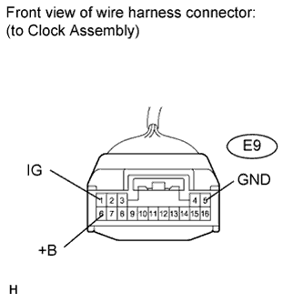
Disconnect the E9 connector.
-
Measure the voltage according to the value(s) in the table below.
Standard voltage Tester Connection Condition Specified Condition E9-1 (IG) - Body ground Ignition switch off Below 1 V Ignition switch on (IG) 11 to 14 V E9-6 (+B) - Body ground Always 11 to 14 V Tip:If the value is not as specified, repair or replace the wire harness or connector.
-
Measure the resistance according to the value(s) in the table below.
Standard resistance Tester Connection Condition Specified Condition E9-5 (GND) - Body ground Always Below 1 Ω Tip:If the value is not as specified, repair or replace the wire harness or connector.
-
- Click here
INSPECT CLOCK ASSEMBLY (w/ Multi-information Display)
-
Ignition switch off.
-
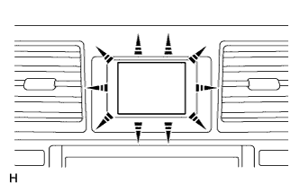
Press the "DISP" button and hold it down.
-
Ignition switch on (IG).
OK All the dots in the multi-information display come on. Tip:This test is also available on "Active Test" (Click here).
-
Ignition switch off to finish this test mode.
Tip:If the result is not as specified, replace the clock assembly (Click here).
-