Click here
-
TELEVISION CAMERA ASSEMBLY
-

Disconnect the S1 camera connector.
-
Measure the voltage of each terminal of the wire harness side connector.
Terminal No. (Symbols) Wiring Color Terminal Description Condition Specified Condition S1-3 (CGND) - Body ground W - Body ground Ground Always Below 1 V S1-4 (CB+) - S1-3 (CGND) B - W Power source Ignition switch on (IG)
Shift lever R position
Approx. 6 V If the result is not as specified, there may be a malfunction on the wire harness side.
-
Reconnect the S1 camera connector.
-
Measure the voltage and frequency of each terminal of the connector.
Terminal No. (Symbols) Wiring Color Terminal Description Condition Specified Condition S1-1 (CV-) - S1-2 (CV+) BR - R Display signal Ignition switch on (IG)
Shift lever R position
Pulse generation
(See waveform 1)
If the result is not as specified, the camera may have a malfunction.
-

Reference:
Oscilloscope waveform
-
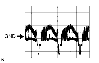
Waveform 1
Item Content Measure terminal S1-1 (CV-) - S1-2 (CV+) Measure set 0.2 V/DIV., 0.2 μS/DIV. Condition Ignition switch: on (IG), Shift lever: R position
-
-
-

CLOCK ASSEMBLY (Multi-Information Display)
Terminal No. (Symbols) Wiring Color Terminal Description Condition Specified Condition E9-1 (IG) - E9-5 (GND) P - W-B Ignition switch signal Ignition switch off Below 1 V Ignition switch on (IG) 11 to 14 V E9-2 (REV) - E9-5 (GND) R - W-B Reverse signal Ignition switch on (IG)
Shift lever except R position
Below 1 V Ignition switch on (IG)
Shift lever R position
11 to 14 V E9-4 (CGND) - E9-5 (GND) W - W-B Television camera ground Always Below 1 V E9-5 (GND) - Body ground W-B - Body ground Ground Always Below 1 V E9-6 (+B) - E9-5 (GND) Y - W-B Battery Always 11 to 14 V E9-12 (CA+) - E9-5 (GND) B - W-B Power source to television camera Ignition switch on (IG)
Shift lever R position
Approx. 6 V E9-14 (V+) - E9-5 (GND) R - W-B Television camera display signal (Input) Ignition switch on (IG)
Shift lever R position
Pulse generation
(See waveform 1)
E9-15 (V-) - E9-5 (GND) Shielded - W-B Television camera ground (Shielded) Always Below 1 V E9-16 (SGND) - Body ground BR - Body ground Signal ground Always Below 1 V
-
Reference:
Oscilloscope waveform
-
Waveform 1
Item Content Measure terminal E9-14 (V+) - E9-15 (V-) Measure set 0.2 V/DIV., 0.2 μS/DIV. Condition Ignition switch: on (IG), Shift lever: R position
-
-