REAR VIEW MONITOR SYSTEM (w/ Navigation System) Display Signal Circuit between Navigation Receiver Assembly and Television Camera Assembly
DESCRIPTION
The display signal from the television camera assembly is transmitted to the navigation receiver assembly.
WIRING DIAGRAM
-
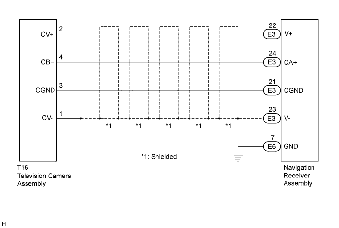
w/ Navigation System (for DVD)
-
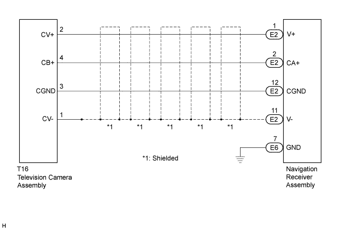
w/ Navigation System (for HDD)
INSPECTION PROCEDURE
PROCEDURE
-
CONFIRM MODEL
-
Choose the model to be inspected.
Result Model Proceed to w/ Navigation system (for DVD) A w/ Navigation system (for HDD) B
B 
CHECK HARNESS AND CONNECTOR (NAVIGATION RECEIVER ASSEMBLY - TELEVISION CAMERA ASSEMBLY) Click here
A 
-
-
CHECK HARNESS AND CONNECTOR (NAVIGATION RECEIVER ASSEMBLY - TELEVISION CAMERA ASSEMBLY)
-
Disconnect the E3 navigation receiver assembly.
-
Disconnect the T16 television camera assembly.
-
Measure the resistance according to the value(s) in the table below.
Standard Resistance Tester Connection Condition Specified Condition T16-2 (CV+) - E3-22 (V+) Always Below 1 Ω T16-4 (CB+) - E3-24 (CA+) Always Below 1 Ω T16-3 (CGND) - E3-21 (CGND) Always Below 1 Ω T16-1 (CV-) - E3-23 (V-) Always Below 1 Ω T16-2 (CV+) - Body ground Always 10 kΩ or higher T16-4 (CB+) - Body ground Always 10 kΩ or higher T16-3 (CGND) - Body ground Always 10 kΩ or higher T16-1 (CV-) - Body ground Always 10 kΩ or higher
NG 
REPAIR OR REPLACE HARNESS OR CONNECTOR
OK
-
-
INSPECT NAVIGATION RECEIVER ASSEMBLY
-
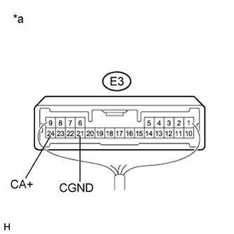
Text in Illustration *a Component with harness connected
(Navigation Receiver Assembly)
Reconnect the E3 navigation receiver assembly.
-
Measure the voltage according to the value(s) in the table below.
Standard Voltage Tester Connection Condition Specified Condition E3-24 (CA+) - E3-21 (CGND) Ignition switch ON
Shift lever in R
5.5 to 7.05 V
NG
REPLACE NAVIGATION RECEIVER ASSEMBLY Click here
OK
-
-
INSPECT TELEVISION CAMERA ASSEMBLY
-
Reconnect the T16 television camera assembly.
-
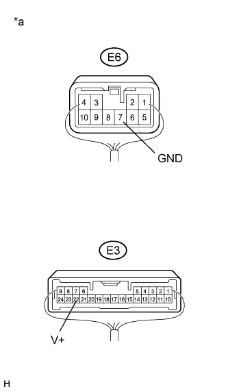
Text in Illustration *a Component with harness connected
(Navigation Receiver Assembly)
Check that the E6 and E3 connectors are connected to the navigation receiver assembly.
-
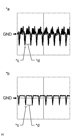
Text in Illustration *a Waveform 1 (camera lens not covered, displaying an image) *b Waveform 2 (camera lens covered, blacking out the screen) *c Synchronization Signal *d Video Waveform Check the waveform of the television camera assembly using an oscilloscope.
Tech Tips
A waterproof connector is used for the rear television camera assembly. Therefore, inspect the waveform at the navigation receiver assembly with the connector connected.
OK Waveform is similar to that shown in the illustration. Item Content Terminal No. (Symbol) E3-22 (V+) - E6-7 (GND) Tool Setting 200 mV/DIV., 50 μsec./DIV. Condition Ignition switch ON, shift lever in R Tech Tips
The video waveform changes according to the image sent by the television camera assembly.
NG
REPLACE TELEVISION CAMERA ASSEMBLY Click here
OK 
PROCEED TO NEXT SUSPECTED AREA SHOWN IN PROBLEM SYMPTOMS TABLE Click here
-
-
CHECK HARNESS AND CONNECTOR (NAVIGATION RECEIVER ASSEMBLY - TELEVISION CAMERA ASSEMBLY)
-
Disconnect the E2 navigation receiver assembly.
-
Disconnect the T16 television camera assembly.
-
Measure the resistance according to the value(s) in the table below.
Standard Resistance Tester Connection Condition Specified Condition T16-2 (CV+) - E2-1 (V+) Always Below 1 Ω T16-4 (CB+) - E2-2 (CA+) Always Below 1 Ω T16-3 (CGND) - E2-12 (CGND) Always Below 1 Ω T16-1 (CV-) - E2-11 (V-) Always Below 1 Ω T16-2 (CV+) - Body ground Always 10 kΩ or higher T16-4 (CB+) - Body ground Always 10 kΩ or higher T16-3 (CGND) - Body ground Always 10 kΩ or higher T16-1 (CV-) - Body ground Always 10 kΩ or higher
NG
REPAIR OR REPLACE HARNESS OR CONNECTOR
OK
-
-
INSPECT NAVIGATION RECEIVER ASSEMBLY
-
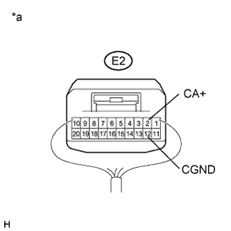
Text in Illustration *a Component with harness connected
(Navigation Receiver Assembly)
Reconnect the E2 navigation receiver assembly.
-
Measure the voltage according to the value(s) in the table below.
Standard Voltage Tester Connection Condition Specified Condition E2-2 (CA+) - E2-12 (CGND) Ignition switch ON
Shift lever in R
5.5 to 7.05 V
NG
REPLACE NAVIGATION RECEIVER ASSEMBLY Click here
OK
-
-
INSPECT TELEVISION CAMERA ASSEMBLY
-
Reconnect the T16 television camera assembly.
-
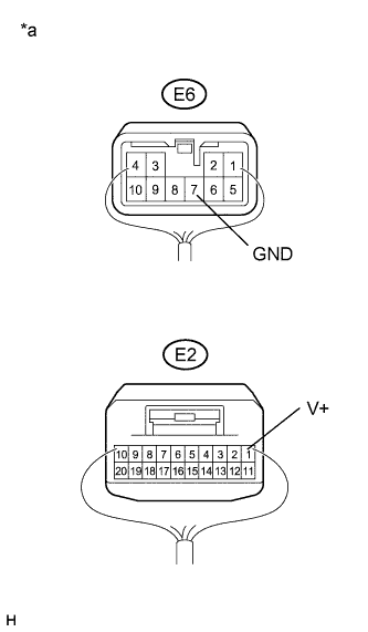
Text in Illustration *a Component with harness connected
(Navigation Receiver Assembly)
Check that the E6 and E2 connectors are connected to the navigation receiver assembly.
-
Text in Illustration *a Waveform 1 (camera lens not covered, displaying an image) *b Waveform 2 (camera lens covered, blacking out the screen) *c Synchronization Signal *d Video Waveform Check the waveform of the television camera assembly using an oscilloscope.
Tech Tips
A waterproof connector is used for the rear television camera assembly. Therefore, inspect the waveform at the navigation receiver assembly with the connector connected.
OK Waveform is similar to that shown in the illustration. Item Content Terminal No. (Symbol) E2-1 (V+) - E6-7 (GND) Tool Setting 200 mV/DIV., 50 μsec./DIV. Condition Ignition switch ON, shift lever in R Tech Tips
The video waveform changes according to the image sent by the television camera assembly.
NG
REPLACE TELEVISION CAMERA ASSEMBLY Click here
OK
PROCEED TO NEXT SUSPECTED AREA SHOWN IN PROBLEM SYMPTOMS TABLE Click here
-