REAR VIEW MONITOR SYSTEM (w/ Navigation System) Display Signal Circuit between Navigation Receiver Assembly and Television Camera Assembly
DESCRIPTION
This is the display signal circuit of the television camera assembly.
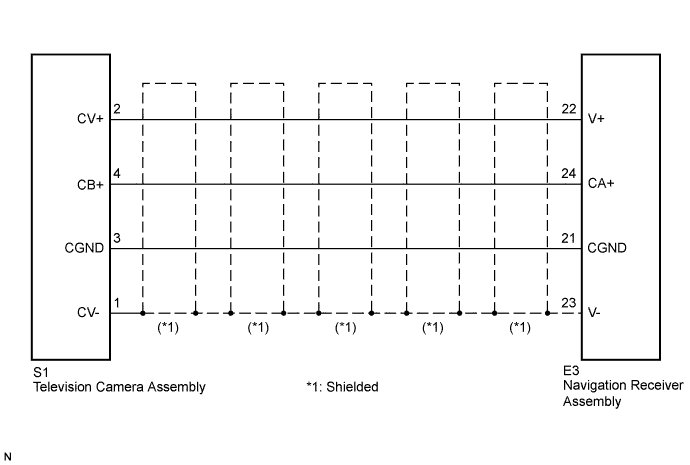
WIRING DIAGRAM
INSPECTION PROCEDURE
PROCEDURE
-
CHECK HARNESS AND CONNECTOR (NAVIGATION RECEIVER ASSEMBLY - TELEVISION CAMERA ASSEMBLY)
-
Disconnect navigation receiver assembly connector E3.
-
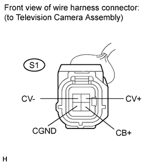
Disconnect television camera assembly connector S1.
-
Measure the resistance according to the value(s) in the table below.
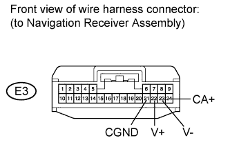
Standard resistance Tester Connection Condition Specified Condition S1-2 (CV+) - E3-22 (V+) Always Below 1 Ω S1-4 (CB+) - E3-24 (CA+) Always Below 1 Ω S1-3 (CGND) - E3-21 (CGND) Always Below 1 Ω S1-1 (CV-) - E3-23 (V-) Always Below 1 Ω S1-2 (CV+) - Body ground Always 10 kΩ or higher S1-4 (CB+) - Body ground Always 10 kΩ or higher S1-3 (CGND) - Body ground Always 10 kΩ or higher S1-1 (CV-) - Body ground Always 10 kΩ or higher
NG 
REPAIR OR REPLACE HARNESS OR CONNECTOR
OK 
-
-
INSPECT NAVIGATION RECEIVER ASSEMBLY
-
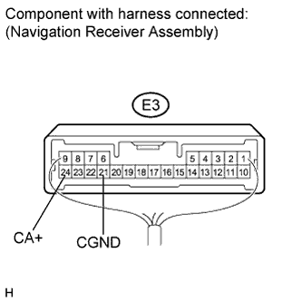
Reconnect navigation receiver assembly connector E3.
-
Measure the voltage according to the value(s) in the table below.
Standard voltage Tester Connection Condition Specified Condition E3-24 (CA+) - E3-21 (CGND) Ignition switch on (IG)
Shift lever R position
Approx. 6 V
NG
REPLACE NAVIGATION RECEIVER ASSEMBLY Click here
OK
-
-
INSPECT TELEVISION CAMERA ASSEMBLY
-
Reconnect navigation receiver assembly connector E3 and television camera assembly connector S1.
-
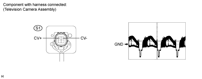
Check the waveform of the television camera assembly using an oscilloscope.
OK Pulses as shown in the illustration. Item Content Terminal No. (Symbols) S1-2 (CV+) - S1-1 (CV-) Tool 0.2 V/DIV., 0.2 μsec./DIV. Condition Ignition switch on (IG), shift lever R position
NG
REPLACE TELEVISION CAMERA ASSEMBLY Click here
OK 
PROCEED TO NEXT CIRCUIT INSPECTION SHOWN IN PROBLEM SYMPTOMS TABLE Click here
-