REAR VIEW MONITOR SYSTEM (w/ Navigation System) TERMINALS OF ECU
-
TELEVISION CAMERA ASSEMBLY
-
Disconnect the S1 camera connector.

-
Measure the voltage of each terminal of the wire harness side connector.
Terminal No. (Symbols) Wiring Color Terminal Description Condition Specified Condition S1-3 (CGND) - Body ground W - Body ground Ground Always Below 1 V S1-4 (CB+) - S1-3 (CGND) B - W Power source Ignition switch on (IG), shift lever R position Approx. 6 V If the result is not as specified, there may be a malfunction on the wire harness side.
-
Reconnect the S1 camera connector.
-
Measure the voltage and frequency of each terminal of the connector.
Terminal No. (Symbols) Wiring Color Terminal Description Condition Specified Condition S1-1 (CV-) - S1-2 (CV+) BR - R Display signal Ignition switch on (IG), shift lever R position See waveform 1 If the result is not as specified, the camera may have a malfunction.
-
Reference:
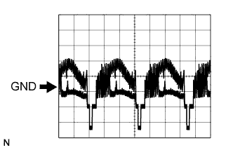
Oscilloscope waveform
-
Waveform 1
Item Content Measure terminal S1-1 (CV-) - S1-2 (CV+) Measure set 0.2 V/DIV., 0.2 μS/DIV. Condition Ignition switch: on (IG), Shift lever: R position
-
-
-
NAVIGATION RECEIVER ASSEMBLY Click here