PARKING ASSIST MONITOR SYSTEM Display Signal Circuit between Television Camera ECU and Television Camera Assembly
DESCRIPTION
This is the display signal circuit of the television camera.
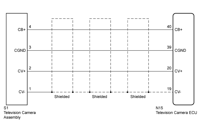
WIRING DIAGRAM
INSPECTION PROCEDURE
PROCEDURE
-
CHECK HARNESS AND CONNECTOR (TELEVISION CAMERA ECU - TELEVISION CAMERA)
-

Disconnect television camera ECU connector N15.
-
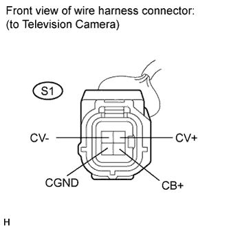
Disconnect television camera connector S1.
-
Measure the resistance according to the value(s) in the table below.
Standard resistance Tester Connection Condition Specified Condition N15-40 (CB+) - S1-4 (CB+) Always Below 1 Ω N15-39 (CGND) - S1-3 (CGND) Below 1 Ω N15-20 (CV+) - S1-2 (CV+) Below 1 Ω N15-19 (CV-) - S1-1 (CV-) Below 1 Ω N15-40 (CB+) - Body ground 10 kΩ or higher N15-39 (CGND) - Body ground 10 kΩ or higher N15-20 (CV+) - Body ground 10 kΩ or higher N15-19 (CV-) - Body ground 10 kΩ or higher
NG 
REPAIR OR REPLACE HARNESS OR CONNECTOR
OK 
-
-
INSPECT TELEVISION CAMERA ECU
-
Reconnect television camera ECU connector N15.
-
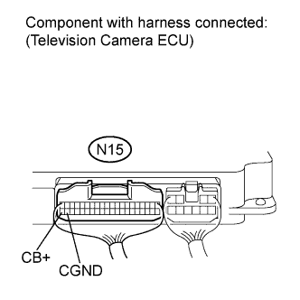
Measure the voltage of the camera.
Standard voltage Tester Connection Condition Specified Condition N15-40 (CB+) - N15-39 (CGND) Ignition switch on (IG), shift lever in reverse position Approx. 6 V
NG
REPLACE TELEVISION CAMERA ECU Click here
OK
-
-
INSPECT TELEVISION CAMERA ASSEMBLY
-
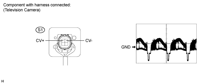
Reconnect television camera connector S1.
-
Check the waveform of the television camera using an oscilloscope.
OK Waveform is as shown in the illustration. Item Content Terminal No. (Symbols) S1-2 (CV+) - S1-1 (CV-) Tool 0.2 V/DIV., 0.2 μsec./DIV. Condition Ignition switch on (IG), shift lever reverse position
NG
REPLACE TELEVISION CAMERA ASSEMBLY Click here
OK 
PROCEED TO NEXT CIRCUIT INSPECTION SHOWN IN PROBLEM SYMPTOMS TABLE Click here
-