Click here
| DTC Code | DTC Name |
|---|---|
| 5C-40 | Camera Picture Error |
Click here
DESCRIPTION
| DTC | DTC Detection Condition | Trouble Area |
|---|---|---|
| 5C-40 | Synchronous signals from the camera cannot be transmitted. |
|
Click here
INSPECTION PROCEDURE
Click here
PROCEDURE
- Click here
CHECK HARNESS AND CONNECTOR (TELEVISION CAMERA ECU - TELEVISION CAMERA)
-

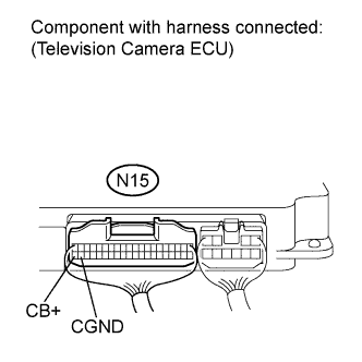
Disconnect television camera ECU connector N15.
-
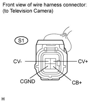
Disconnect television camera connector S1.
-
Measure the resistance according to the value(s) in the table below.
Standard resistance Tester Connection Condition Specified Condition N15-40 (CB+) - S1-4 (CB+) Always Below 1 Ω N15-39 (CGND) - S1-3 (CGND) Below 1 Ω N15-20 (CV+) - S1-2 (CV+) Below 1 Ω N15-19 (CV-) - S1-1 (CV-) Below 1 Ω N15-40 (CB+) - Body ground 10 kΩ or higher N15-39 (CGND) - Body ground 10 kΩ or higher N15-20 (CV+) - Body ground 10 kΩ or higher N15-19 (CV-) - Body ground 10 kΩ or higher
- OKClick here
- NGClick here
-
- Click here
INSPECT TELEVISION CAMERA ECU
-
Reconnect television camera ECU connector N15.
-
Measure the voltage of the camera.
Standard voltage Tester Connection Condition Specified Condition N15-40 (CB+) - N15-39 (CGND) Ignition switch on (IG), shift lever in reverse position Approx. 6 V
- OKClick here
- NGClick here
-
-
Click here
INSPECT TELEVISION CAMERA ASSEMBLY
-
Reconnect television camera connector S1.
-
Check the waveform of the television camera using an oscilloscope.
OK Waveform is as shown in the illustration. Item Content Terminal No. (Symbols) S1-2 (CV+) - S1-1 (CV-) Tool 0.2 V/DIV., 0.2 μsec./DIV. Condition Ignition switch on (IG), shift lever reverse position
- OKClick here
- NGClick here
-
- Click here
REPLACE TELEVISION CAMERA ECUClick here
- Click here
REPAIR OR REPLACE HARNESS OR CONNECTOR
- Click here
REPLACE TELEVISION CAMERA ECUClick here
- Click here
REPLACE TELEVISION CAMERA ASSEMBLYClick here