Click here
-
GENERAL
-
This system has a television camera mounted on the back door to display the view of the area behind the vehicle on the navigation receiver assembly. The display panel also shows a composite view consisting of the area behind the vehicle and parking guidelines to assist the driver in parking the vehicle by monitoring the area behind the vehicle.
-
This system consists of the following components: television camera ECU, television camera, navigation receiver assembly, ECM, skid control ECU, and steering angle sensor.
-
This system is equipped with a self-diagnosis system, which is operated on a designated window that appears on the display panel, just as in the navigation system.
-
-
FUNCTION OF COMPONENTS
-
The television camera ECU controls the system by using information from the following components.
Item Function Television camera
-
Mounted on the back door to transmit the rear view of the vehicle to the television camera ECU.
-
A color video camera that uses a CCD (Charge Coupled Device) and a wide- angle lens.
Television camera ECU
-
Transmits video signals, which contain a composite of the rear view of the vehicle taken with the television camera and the parking assist guidelines, to the multi-display (navigation receiver assembly).
-
Effects overall control of the system by receiving signals from the sensors and the navigation receiver assembly.
Navigation receiver assembly
-
Receives video signals containing a composite of the rear view of the vehicle and the parking assist guideline signals from the television camera ECU, and displays them on the display panel.
-
Uses the yaw rate detected by the gyro sensor that is built into the navigation ECU to transmit the movement of the vehicle to the television camera ECU.
Steering angle sensor Detects the angle of the steering wheel and sends the resulting signals to the television camera ECU through CAN communication. Skid control ECU Transmits vehicle speed signals. ECM Transmits reverse signals. -
-
-
OPERATION EXPLANATION
-
When the shift lever is moved to the R position, the ECM recognizes the reverse position signal.
The ECM sends the reverse position signal to the television camera ECU via CAN communication.
After receiving the reverse position signal, the television camera ECU switches the current screen on the navigation receiver assembly to the parking assist monitor screen.
-
In parallel parking assist mode, appropriate steering angle and timing information can be provided for the driver when parallel parking. This is based on the information from the steering angle sensor signal and the vehicle angle data signal that are sent to the television camera ECU.
Tip:
-
In manual assist mode, the steering angle sensor signal and the vehicle angle data signal are not used to control parking assist.
-
The vehicle speed signal is required to adjust the steering angle neutral point.
-
-
-
COMMUNICATION SYSTEM
-

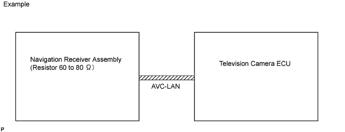
This parking assist monitor system communicates between its components by AVC-LAN. Also, "PARALLEL PARKING ASSIST MODE" judges the vehicle angle data transmitted via AVC-LAN from the navigation receiver assembly (the data is calculated by the navigation receiver assembly through integrating the yaw rate detected by the gyro sensor built into the navigation receiver assembly).
-
-
DIAGNOSTIC FUNCTION
-
This parking assist monitor system has a diagnostic function (displayed in "NAVIGATION SYSTEM" of the navigation receiver assembly).
-
A 3-digit "unit code (physical address)" number (in hexadecimal notation) is set in each component that makes up the AVC-LAN.
-
A 2-digit "logical address" number (in hexadecimal notation) is set in each function of the components that makes up the AVC-LAN.
-
-
AVC-LAN DESCRIPTION
-
What is AVC-LAN?
AVC-LAN, an abbreviation for "Audio Visual Communication Local Area Network", is a united standard developed by the manufacturers in affiliation with Toyota Motor Corporation. This standard pertains to audio and visual signals as well as switch and communication signals.
-
Purpose:
Recently, car audio systems have rapidly developed and the functions vastly changed. The conventional car audio system is being integrated with multi-media interfaces similar to those in navigation systems. At the same time, customers are demanding higher quality from their audio systems. This is merely an overview of the standardization background. The specific purposes are as follows:
-
To solve sound problems, etc. caused by using components of different manufacturers through signal standardization.
-
To allow each manufacturer to concentrate on developing products they do best. From this, reasonably priced products can be produced.
Tip:
-
If a +B or GND short is detected in the AVC-LAN circuit, communication is interrupted and the audio system will stop functioning.
-
If the audio system is equipped with the navigation system, the multi-display unit acts as the master unit. If the audio system is not equipped with the navigation system, the audio head unit acts as the master unit instead. If the audio system is equipped with the navigation receiver assembly, it is the master unit.
-
The navigation receiver assembly provides resistance to make communication possible.
-
A car audio system with an AVC-LAN circuit has a diagnostic function.
-
Each component has a specified number (3-digit) called a physical address. Each function has a number (2-digit) called a logical address.
-
-
-
-
NOTES FOR PARKING ASSIST MONITOR
-
Notes for the parking assist monitor:
-
The parking assist monitor may not function properly if subjected to a severe blow by a hard object.
-
Do not "scrub" the cover part of the camera (resin made). Scrubbing it may scratch the cover and affect the image. Prevent organic solvents, waxes, bond removing solvents, or glass coating from adhering to the cover. If such material adheres to the cover, clean it off immediately and wash with water.
-
Exposing the camera to sudden temperature changes may affect proper function.
-
A clear image may not appear if the camera is dirty with snow, mud, etc. If the lens is dirty, wash it with water and wipe off to clean the lens. Use a detergent to remove dirt if necessary.
-
-
Images will be difficult to discern even in normal conditions if:
-
The display screen is frosted over (the image immediately after turning the ignition switch on (IG) may be blurred or darker than normal).
-
A strong beam of light, such as a sunbeam or headlight, hits the camera.
-
It is too dark around the camera (at night, for example).
-
The ambient temperature around the camera is either too high or too low.
Tip:When a strong light, such as a sunbeam reflected off a vehicle's body, hits the camera, the image may be blurred. This is called the "SMEAR" phenomenon, peculiar to the CCD camera.
-
-