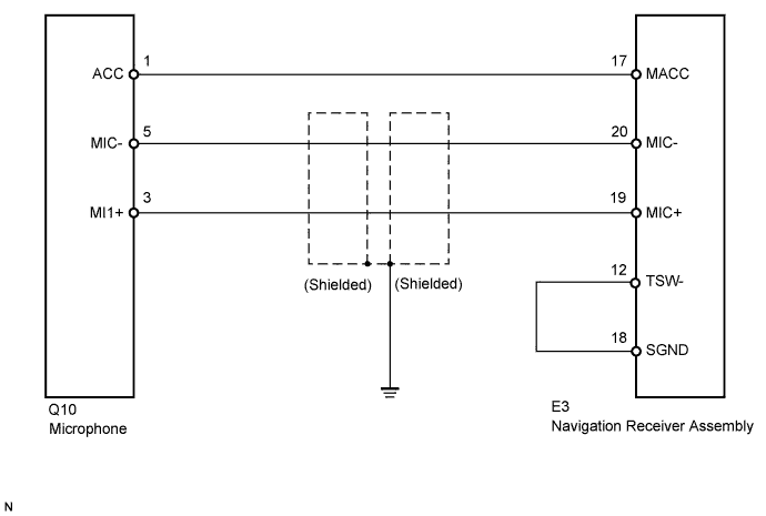
NAVIGATION SYSTEM (for DVD) Microphone Circuit between Microphone and Navigation Receiver Assembly
DESCRIPTION
This circuit sends a microphone signal from the overhead junction block (microphone) to the navigation receiver assembly.
It also supplies power from the navigation receiver assembly to the overhead junction block (microphone).
WIRING DIAGRAM
INSPECTION PROCEDURE
PROCEDURE
-
CHECK HARNESS AND CONNECTOR (OVERHEAD JUNCTION BLOCK - NAVIGATION RECEIVER ASSEMBLY)
-
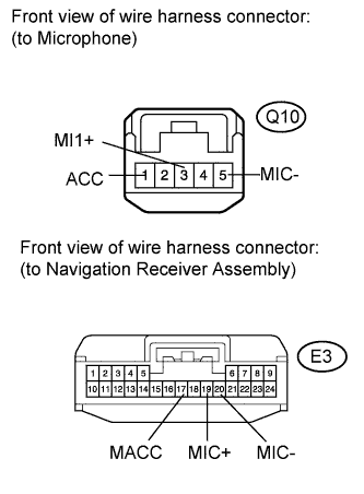
Disconnect microphone connector Q10 and navigation receiver assembly connector E3.
-
Measure the resistance according to the value(s) in the table below.
Standard resistance Tester Connection Condition Specified Condition Q10-1 (ACC) - E3-17 (MACC) Always Below 1 Ω Q10-3 (MI1+) - E3-19 (MIC+) Always Below 1 Ω Q10-5 (MIC-) - E3-20 (MIC-) Always Below 1 Ω E3-17 (MACC) - Body ground Always 10 kΩ or higher E3-19 (MIC+) - Body ground Always 10 kΩ or higher E3-20 (MIC-) - Body ground Always 10 kΩ or higher
NG 
REPAIR OR REPLACE HARNESS OR CONNECTOR
OK 
-
-
INSPECT NAVIGATION RECEIVER ASSEMBLY
-
Measure the voltage according to the value(s) in the table below.
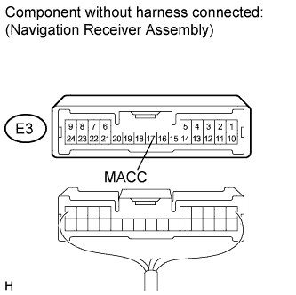
Standard voltage Tester Connection Condition Specified Condition E3-17 (MACC) - Body ground Ignition switch on (ACC) 4 to 6 V
NG
REPLACE NAVIGATION RECEIVER ASSEMBLY Click here
OK
-
-
CHECK HARNESS AND CONNECTOR (NAVIGATION RECEIVER ASSEMBLY)
-
Measure the resistance according to the value(s) in the table below.
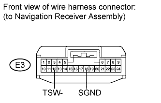
Standard resistance Tester Connection Condition Specified Condition E3-12 (TSW-) - E3-18 (SGND) Always Below 1 Ω
NG
REPAIR OR REPLACE HARNESS OR CONNECTOR
OK 
PROCEED TO NEXT CIRCUIT INSPECTION SHOWN IN PROBLEM SYMPTOMS TABLE Click here
-