NAVIGATION SYSTEM (for DVD) Reverse Signal Circuit
DESCRIPTION
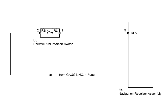
The navigation receiver assembly receives a reverse signal from the park/neutral position switch and information about the GPS antenna, and then adjusts the vehicle position on the navigation display.
WIRING DIAGRAM
INSPECTION PROCEDURE
PROCEDURE
-
INSPECT NAVIGATION RECEIVER ASSEMBLY
-
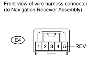
Disconnect navigation receiver assembly connector E4.
-
Measure the voltage according to the value(s) in the table below.
Standard voltage Tester Connection Condition Specified Condition E4-5 (REV) - Body ground Ignition switch on (IG)
Shift lever R position
11 to 14 V E4-5 (REV) - Body ground Ignition switch on (IG)
Shift lever any position except R
Below 1 V
NG 
CHECK HARNESS AND CONNECTOR (NAVIGATION RECEIVER ASSEMBLY - PARK/NEUTRAL POSITION SWITCH) Click here
OK 
REPLACE NAVIGATION RECEIVER ASSEMBLY Click here
-
-
CHECK HARNESS AND CONNECTOR (NAVIGATION RECEIVER ASSEMBLY - PARK/NEUTRAL POSITION SWITCH)
-
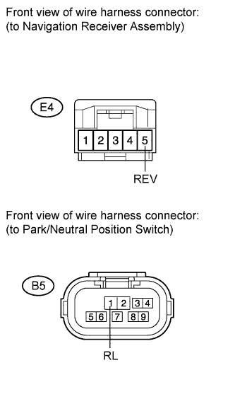
Disconnect navigation receiver assembly connector E4.
-
Disconnect park/neutral position switch connector B5.
-
Measure the resistance according to the value(s) in the table below.
Standard resistance Tester Connection Condition Specified Condition E4-5 (REV) - B5-1 (RL) Always Below 1 Ω E4-5 (REV) - Body ground Always 10 kΩ or higher
NG 
REPAIR OR REPLACE HARNESS OR CONNECTOR
OK 
-
-
CHECK HARNESS AND CONNECTOR (PARK/NEUTRAL POSITION SWITCH - BATTERY)
-
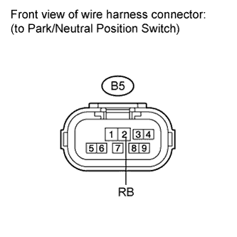
Measure the voltage according to the value(s) in the table below.
Standard voltage Tester Connection Condition Specified Condition B5-2 (RB) - Body ground Ignition switch on (IG) 11 to 14 V Result Result Proceed to NG A OK (for U151E) B OK (for U151F) C
B
REPLACE PARK/NEUTRAL POSITION SWITCH (for U151E) Click here
C
REPLACE PARK/NEUTRAL POSITION SWITCH (for U151F) Click here
A
REPAIR OR REPLACE HARNESS OR CONNECTOR
-