NAVIGATION SYSTEM (for HDD) TERMINALS OF ECU
-
NAVIGATION RECEIVER ASSEMBLY
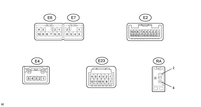
Terminal No. (Symbol) Wiring Color Terminal Description Condition Specified Condition E6-1 (FR+) - E6-7 (GND) LG - BR Sound signal (Front right) Audio system playing A waveform synchronized with sounds is output E6-2 (FL+) - E6-7 (GND) P - BR Sound signal (Front left) Audio system playing A waveform synchronized with sounds is output E6-3 (ACC) - E6-7 (GND) GR - BR Accessory (ON) Ignition switch off Below 1 V Ignition switch ACC 11 to 14 V E6-4 (B) - E6-7 (GND) B - BR Battery Ignition switch off 11 to 14 V E6-5 (FR-) - E6-7 (GND) L - BR Sound signal (Front right) Audio system playing A waveform synchronized with sounds is output E6-6 (FL-) - E6-7 (GND) V - BR Sound signal (Front left) Audio system playing A waveform synchronized with sounds is output E6-7 (GND) - Body ground BR - Body ground Ground Always Below 1 V E6-10 (ILL+) - E6-7 (GND) G - BR Illumination signal Ignition switch ON
Light control switch off → tail or on
Below 1 V → 11 to 14 V E7-1 (RR+) - E6-7 (GND) R - BR Sound signal (Rear right) Audio system playing A waveform synchronized with sounds is output E7-2 (RL+) - E6-7 (GND) B - BR Sound signal (Rear left) Audio system playing A waveform synchronized with sounds is output E7-3 (RR-) - E6-7 (GND) W - BR Sound signal (Rear right) Audio system playing A waveform synchronized with sounds is output E7-6 (RL-) - E6-7 (GND) Y - BR Sound signal (Rear left) Audio system playing A waveform synchronized with sounds is output E2-1 (V+) - E6-7 (GND) R - BR Television camera image signal Ignition switch ON
Shift lever in R
Camera lens is not covered, displaying an image
Pulse generation (Refer to waveform 1) Ignition switch ON
Shift lever in R
Camera lens is covered, blacking out screen
Pulse generation (Refer to waveform 2) E2-2 (CA+) - E6-7 (GND) B - BR Television camera power supply Ignition switch ON
Shift lever in R
5.5 to 7 V E2-3 (SNS2) - E6-7 (GND) G - BR Microphone connection detection signal Always Below 1 V E2-4 (MIN+) - E6-7 (GND) B - BR Microphone voice signal See "Microphone & Voice Recognition Check" in Operation Check Click here
- E2-5 (MACC) - E6-7 (GND) W - BR Telephone microphone assembly power supply Ignition switch off Below 1 V Ignition switch ACC 4 to 6 V E2-6 (SWG) - Body ground B - Body ground Steering pad switch signal Always Below 1 V E2-7 (SW1) - E2-6 (SWG) BE - B Steering pad switch signal No switch pushed →
MODE switch pushed →
ON HOOK switch pushed →
OFF HOOK switch pushed →
VOICE switch pushed
4.44 to 5.43 V →
0.45 to 0.65 V →
1.19 to 1.49 V →
2.09 to 2.54 V →
3.2 to 3.88V
E2-8 (SW2) - E2-6 (SWG) V - B Steering pad switch signal No switch is pushed →
SEEK+ switch pushed →
SEEK- switch pushed →
VOL+ switch pushed →
VOL- switch pushedd
4.44 to 5.43 V →
0.45 to 0.65 V →
1.19 to 1.49 V →
2.09 to 2.54 V →
3.2 to 3.88 V
E2-11 (V-) - Body ground Shield - Body ground Shield ground Always Below 1 V E2-12 (CGND) - E6-7 (GND) W - BR Ground Always Below 1 V E2-13 (MIN-) - Body ground R - Body ground Microphone voice signal See "Microphone & Voice Recognition Check" in Operation Check Click here
- E2-14 (SGND) - E6-7 (GND) Shield - BR Shield ground Always Below 1 V E2-15 (ARI) - E2-16 (ASGN) R - W Sound signal (Right) External device playing (When stereo jack used) A waveform synchronized with sounds is output E2-16 (ASGN) - E6-7 (GND) W - BR Sound signal ground Always Below 1 V E2-17 (ALI) - E2-16 (ASGN) B - W Sound signal (Left) External device playing (When stereo jack used) A waveform synchronized with sounds is output E2-18 (AGND) - Body ground Shield - Body ground Shield ground Always Below 1 V E2-19 (AUXI) - E6-7 (GND) Y - BR External device connection detection signal External device connected Below 1 V External device not connected 2.1 to 3 V E4-1 (PKB) - E6-7 (GND) LG - BR Parking brake signal See "Vehicle Signal Check Mode" in Operation Check Click here
- E4-2 (IG) - E6-7 (GND) G - BR Power source (IG) Ignition switch off Below 1 V Ignition switch ON 11 to 14 V E4-3 (SPD) - E6-7 (GND) V - BR Speed signal from combination meter assembly See "Vehicle Signal Check Mode" in Operation Check Click here
- E4-5 (REV) - E6-7 (GND) R - BR Reverse signal See "Vehicle Signal Check Mode" in Operation Check Click here
- E23-1 (CSLD) - Body ground Shield - Body ground Shield ground Always Below 1 V E23-2 (CDR+) - E6-7 (GND) BR - BR USB audio system sound signal USB audio system playing A waveform synchronized with sounds is output E23-3 (CDR-) - E6-7 (GND) SB - BR USB audio system sound signal USB audio system playing A waveform synchronized with sounds is output E23-4 (CDL+) - E6-7 (GND) LG - BR USB audio system sound signal USB audio system playing A waveform synchronized with sounds is output E23-5 (CDL-) - E6-7 (GND) P - BR USB audio system sound signal USB audio system playing A waveform synchronized with sounds is output E23-6 (MUTE) - E6-7 (GND) B- BR Mute signal USB audio system playing → Source changed to CD Above 3.5 V → Below 1 V E23-7 (GND) - Body ground L - Body ground Ground Always Below 1 V E23-9 (TXM+) Y AVC-LAN communication signal - - E23-10 (TXM-) V AVC-LAN communication signal - - E23-11 (ACC) - E6-7 (GND) G - BR Accessory (ON) Ignition switch off Below 1 V Ignition switch ACC 11 to 14 V E23-12 (+B) - E6-7 (GND) SB - BR Battery Ignition switch off 11 to 14 V RA-5 (ANT) - E6-7 (GND) - - BR Power source of antenna Ignition switch ON
Radio switch on and AM or FM selected
8 V or higher
-
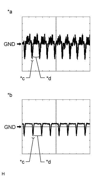
Text in Illustration *a Waveform 1 (camera lens not covered, displaying an image) *b Waveform 2 (camera lens covered, blacking out the screen) *c Synchronization Signal *d Video Waveform Reference (Oscilloscope waveform):
-
Waveform 1 (camera lens is not covered, displaying an image)
Item Content Measurement terminal E2-1 (V+) - E6-7 (GND) Measurement setting 200 mV/DIV., 50 μsec./DIV. Condition Ignition switch ON, Shift lever in R Tech Tips
The video waveform changes according to the image sent by the television camera assembly.
-
Waveform 2 (camera lens is covered, blacking out the screen)
Item Content Measurement terminal E2-1 (V+) - E6-7 (GND) Measurement setting 200 mV/DIV., 50 μsec./DIV. Condition Ignition switch ON, Shift lever in R Tech Tips
The video waveform changes according to the image sent by the rear television camera assembly.
-
-
-
MULTI-MEDIA INTERFACE ECU
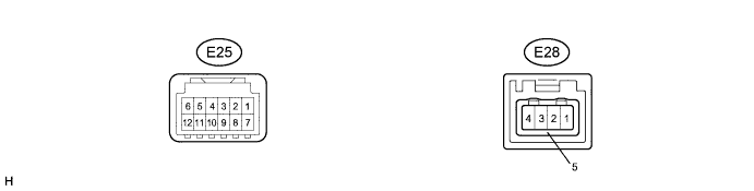
Terminal No. (Symbol) Wiring Color Terminal Description Condition Specification E25-1 (USD1) - Body ground Shield - Body ground Shield ground Always Below 1 V E25-2 (URO+) - E25-7 (GND) BR - L USB audio system sound signal USB audio system playing A waveform synchronized with sounds is output E25-3 (URO-) - E25-7 (GND) SB - L USB audio system sound signal USB audio system playing A waveform synchronized with sounds is output E25-4 (ULO+) - E25-7 (GND) LG - L USB audio system sound signal USB audio system playing A waveform synchronized with sounds is output E25-5 (ULO-) - E25-7 (GND) P - L USB audio system sound signal USB audio system playing A waveform synchronized with sounds is output E25-6 (MUT1) - E25-7 (GND) B - L Mute signal USB audio system playing → Source changed to CD Above 3.5 V → Below 1 V E25-7 (GND) - Body ground L - Body ground Ground Always Below 1 V E25-9 (TX1+) Y AVC-LAN communication signal - - E25-10 (TX1-) V AVC-LAN communication signal - - E25-11 (ACC) - E25-7 (GND) G - L Accessory (ON) Ignition switch off Below 1 V Ignition switch ACC 11 to 14 V E25-12 (+B) - E25-7 (GND) SB - L Battery Ignition switch off 11 to 14 V E28-1 (UESG) - Body ground - - Body ground Ground Always Below 1 V E28-2 (UDI+) - E28-1 (UESG) - Data signal USB device or "iPod" connected - E28-3 (UDI-) - E28-1 (UESG) - Data signal USB device or "iPod" connected - E28-4 (UPO) - E28-1 (UESG) - USB device or "iPod" power supply Ignition switch ACC 5 V E28-5 (UESS) - Body ground Shield - Body ground Shield ground Always Below 1 V