NAVIGATION SYSTEM (for DVD) DIAGNOSIS DISPLAY DETAILED DESCRIPTION
Tech Tips
-
This section contains a detailed description of displays in diagnostic mode.
-
Illustrations may differ from the actual vehicle screen depending on the device settings and options. Therefore, some detailed areas may not be shown exactly the same as on the actual vehicle screen.
-
SYSTEM CHECK
-
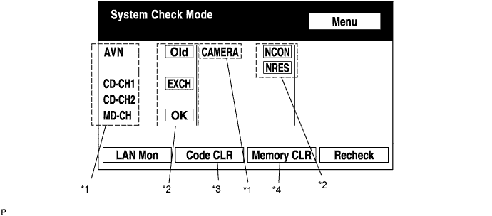
System Check Mode Screen
-
Device Names and Hardware Address/*1
Tech Tips
-
Registered device names are displayed.
-
If a device name is unknown to the system, its physical address is shown instead.
Address No. Name Address No. Name 110 EMV 120 AVX 128 1DIN TV 140 AVN 144 G-BOOK 178 NAVI 17C MONET 190 AUDIO H/U 1AC CAMERA-C 1B0 Rr-TV 1C0 Rr-CONT 19D BT-HF 1C4 PANEL 1C6 G/W 1C8 FM-M-LCD 1D8 CONT-SW 1EC Body 118 EMVN 1F1 XM 1F2 SIRIUS 230 TV-TUNER 240 CD-CH2 250 DVD-CH 280 CAMERA 360 CD-CH1 3A0 MD-CH 17D TEL 440 DSP-AMP 530 ETC 1F6 RSE 1A0 DVD-P 1D6 CLOCK 238 DTV 480 AMP -
-
Check Result/*2
Tech Tips
Result codes for all devices are displayed.
Result Meaning Action OK The device does not respond with a DTC (excluding communication DTCs from the AVC-LAN). - EXCH The device responds with a "replace"-type DTC. Look up the DTC in "Unit Check Mode" and replace the device. CHEK The device responds with a "check"-type DTC. Look up the DTC in "Unit Check Mode". NCON The device was previously present, but does not respond in diagnostic mode.
-
Check power supply wire harness of the device.
-
Check the AVC-LAN of the device.
Old The device responds with an "old"-type DTC. Look up the DTC in "Unit Check Mode". NRES The device responds in diagnostic mode, but gives no DTC information.
-
Check power supply wire harness of the device.
-
Check the AVC-LAN of the device.
-
-
Code Clear/*3
-
Present DTCs are cleared.
-
Press the "Code CLR" switch for 3 seconds.
-
-
Memory Clear/*4
-
Present and past DTCs and registered connected device names are cleared.
-
Press the "Memory CLR" switch for 3 seconds.
-
-
-
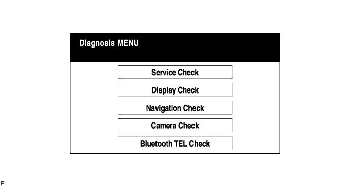
Diagnosis MENU Screen
Tech Tips
Each item is grayed out or not displayed based on the device settings.
-
Unit Check Mode Screen
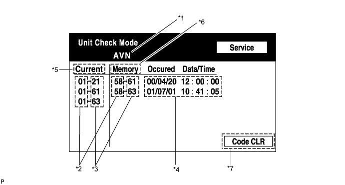
Screen Description: Display Contents Device name/*1 Target device Segment/*2 Target device logical address DTC/*3 DTC (Diagnostic Trouble Code) Timestamp/*4 The time and date of past DTCs are displayed. (The year is displayed in 2-digit format.) Present code/*5 DTCs output in the service check are displayed. Past code/*6 Diagnostic memory results and recorded DTCs are displayed. Diagnosis clear switch/*7 Pushing this switch for 3 seconds clears the diagnostic memory data of the target device. (Both response to diagnostic system check result and the displayed data are cleared.) -
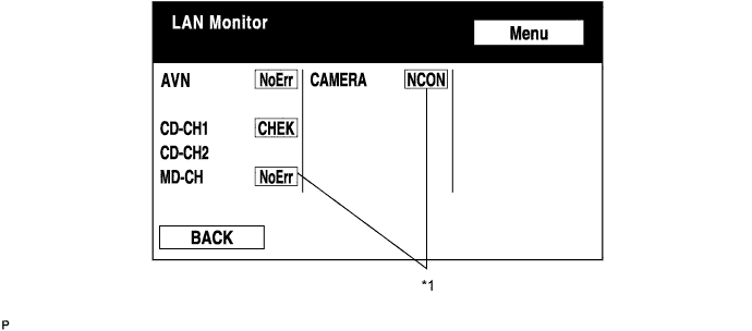
LAN Monitor (Original) Screen
-
Check Result/*1
Tech Tips
Check results of all the devices are displayed.
Result Meaning Action No Err (OK) There are no communication DTCs. - CHEK The device responds with a "check"-type DTC. Look up the DTC in "Unit Check Mode". NCON The device was previously present, but does not respond in diagnostic mode.
-
Check power supply wire harness of the device.
-
Check the AVC-LAN of the device.
Old The device responds with an "old"-type DTC. Look up the DTC in "Unit Check Mode". NRES The device responds in diagnostic mode, but gives no DTC information.
-
Check power supply wire harness of the device.
-
Check the AVC-LAN of the device.
-
-
-
LAN Monitor (Individual) Screen
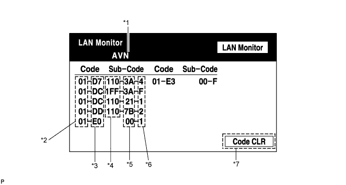
Screen Description: Display Contents Device name/*1 Target device Segment/*2 Target logical address DTC/*3 DTC (Diagnostic Trouble Code) Sub-code (device address)/*4 Physical address stored with DTC (If there is no address, nothing is displayed.) Connection check No./*5 Connection check number stored with DTC DTC occurrence/*6 Number of times the same DTC has been recorded Diagnosis clear switch/*7 Pushing this switch for 3 seconds clears the diagnostic memory data of the target device. (Both response to diagnostic system check result and the displayed data are cleared.)
-
-
DISPLAY CHECK
-
Vehicle Signal Check Mode Screen
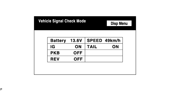
Screen Description: Display Contents Battery Battery voltage is displayed. PKB Parking brake ON/OFF state is displayed. REV Reverse signal ON/OFF state is displayed. IG IG switch ON/OFF state is displayed. TAIL TAIL signal (Light control switch) ON/OFF state is displayed. SPEED Vehicle speed is displayed in km/h. Tech Tips
-
Only items sending vehicle signals will be displayed.
-
This screen is updated once per second when input signals to the vehicle are changed.
-
-
-
NAVIGATION CHECK
-
Navigation Check Screen
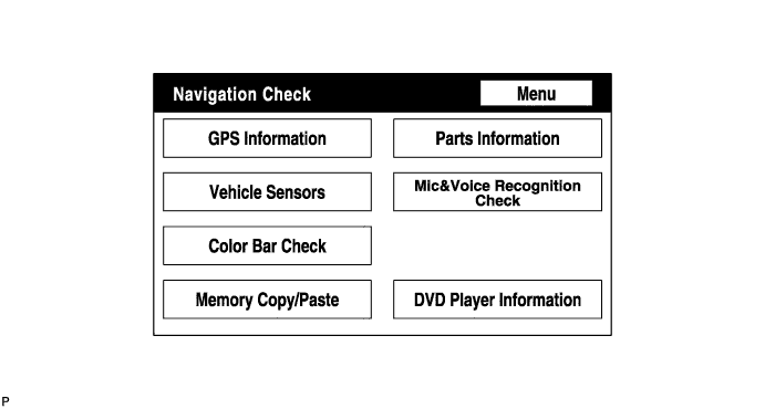
Tech Tips
Each item is grayed out or not displayed based on the device settings.
-
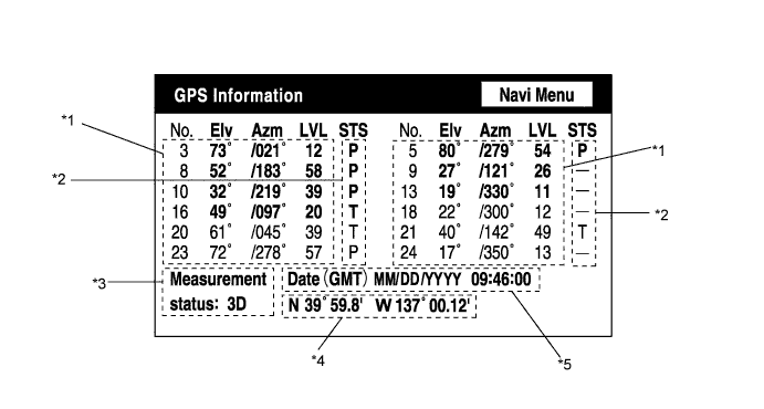
GPS Information Screen
-
Satellite information/*1
Information from a maximum of 12 satellites is displayed on the screen. This information includes the target GPS satellite number, elevation angle, direction, and signal level.
-
Receiving condition/*2
(DENSO model): Display Contents T The system is receiving a GPS signal, but is not using it for location. P The system is using the GPS signal for location. - The system cannot receive a GPS signal. (AISIN AW model): Display Contents 01H The system cannot receive a GPS signal. 02H The system is tracing a satellite. 03H The system is receiving a GPS signal, but is not using it for location. 04H The system is using the GPS signal for location. Measurement information/*3: Display Contents 2D 2-dimensional location method is being used. 3D 3-dimensional location method is being used. NG Location data cannot be used. Error Reception error has occurred. - Any other state. Position information/*4 Display Contents Position Latitude and longitude information on the current position is displayed. Date information/*5: Display Contents Date The date/time information obtained from GPS signal is displayed in Greenwich mean time (GMT). The last 4 digits are displayed.
-
-
Vehicle Sensors Screen
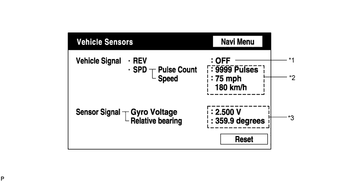
Vehicle signal: Display Contents REV/*1 REV signal ON/OFF state is displayed. SPD/*2 SPD signal condition is displayed. Sensor signal: Display Contents Gyro sensor/*3 Gyro sensor output condition is displayed (when the vehicle runs straight or is stationary, the voltage is approximately 2.5 V). Tech Tips
Signals are updated once per second only when vehicle sensor signals are changed.
-
Microphone & Voice Recognition Check Screen
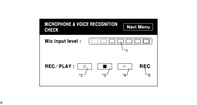
Screen Description: Display Contents Microphone input level meter/*1 Monitors the microphone input level every 100 ms and displays the results in 8 different levels. Recording switch/*2 Starts recording. Stop switch/*3 Stops recording. Play switch/*4 Plays the recorded voice. Recording indicator/*5 Comes on while recording. Tech Tips
-
The microphone input function is on at all times when this screen is displayed.
-
While recording or playing, the switches other than the stop switch cannot be pushed.
-
When no voice is recorded, the play switch cannot be pushed.
-
Recording will stop after 5 seconds or by pushing the stop switch.
-
-
DVD Player Information Screen
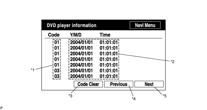
Screen Description: Display Contents Trouble code/*1 Each code corresponding to the malfunctions is displayed. For details, refer to "Trouble Code Description". Occurrence time/*2
-
The date (year, month, day) and time (hour, minute, second) when the trouble code was detected are displayed as a time stamp. (Greenwich mean time)
-
The time data to be displayed are received from the GPS receiver.
Trouble code clear switch/*3 All code data being displayed are cleared by pushing this switch for 3 seconds. Returning switch/*4 The previous page is displayed. If the current displayed page is the first page, this switch cannot be operated. Proceeding switch/*5 The next page is displayed. If the current displayed page is the last page, this switch cannot be operated. Trouble Code Description: Code Malfunction Countermeasure 01 Cannot be recognized Replace navigation receiver assembly. 03 Cannot be read Follow the inspection procedure for DTC 58-42 Click here.
Tech Tips
This is a DVD player check function in the navigation receiver assembly (built-in navigation ECU).
-
-