MULTI-MEDIA INTERFACE ECU REMOVAL
-
PRECAUTION (w/ Navigation System for HDD)
Note
After the ignition switch is turned off, the navigation receiver assembly (HDD navigation system) records various types of memory and settings. As a result, after turning the ignition switch off, make sure to wait at least 60 seconds before disconnecting the cable from the negative (-) battery terminal.
-
DISCONNECT CABLE FROM NEGATIVE BATTERY TERMINAL (w/ Navigation System for HDD)
CAUTION:
Wait at least 90 seconds after disconnecting the cable from the negative (-) battery terminal to disable the SRS system.
Note
When disconnecting the cable, some systems need to be initialized after the cable is reconnected Click here.
-
REMOVE CENTER INSTRUMENT PANEL REGISTER ASSEMBLY
-
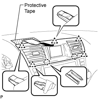
Apply protective tape to the areas shown in the illustration.
-
Using a moulding remover, disengage the 2 claws and 5 clips, and then remove the center instrument panel register assembly as shown in the illustration.
-
-
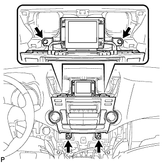
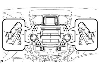
REMOVE CENTER INSTRUMENT CLUSTER FINISH PANEL ASSEMBLY (w/o Smart Entry and Start System)
-
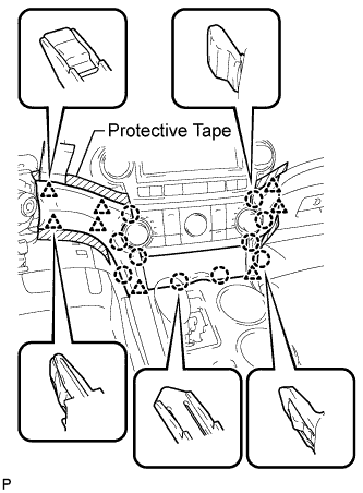
Apply protective tape to the areas shown in the illustration.
-
Using a moulding remover, disengage the 10 claws and 8 clips starting from the upper part of the center instrument cluster finish panel assembly.
Note
Do not pull on the small storage compartment lid. Doing so may cause damage.
-
Disconnect each connector and remove the center instrument cluster finish panel assembly.
-
-
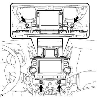
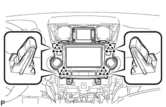
REMOVE CENTER INSTRUMENT CLUSTER FINISH PANEL ASSEMBLY (w/ Smart Entry and Start System)
-
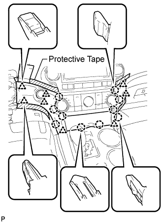
Apply protective tape to the areas shown in the illustration.
-
Using a moulding remover, disengage the 10 claws and 8 clips starting from the upper part of the center instrument cluster finish panel assembly.
Note
Do not pull on the small storage compartment lid. Doing so may cause damage.
-
Disconnect each connector and remove the center instrument cluster finish panel assembly.
-
-
REMOVE HEATER CONTROL AND ACCESSORY ASSEMBLY (for Manual Air Conditioning System)
-

Disengage the 4 clips and remove the heater control and accessory assembly.
-
Disconnect the connector.
-
-
REMOVE AIR CONDITIONING CONTROL ASSEMBLY (for Automatic Air Conditioning System)
-
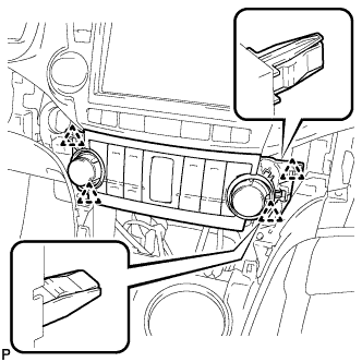
Disengage the 4 clips and remove the air conditioning control assembly.
-
Disconnect the connector.
-
-
REMOVE RADIO RECEIVER ASSEMBLY WITH BRACKET (w/ Radio Receiver)
-
Remove the 4 bolts.
-
Pull the radio receiver assembly with bracket toward the rear of the vehicle and disengage the 4 clips.
-
Disconnect each connector and remove the radio receiver assembly with bracket.
-
-
REMOVE NAVIGATION RECEIVER ASSEMBLY WITH BRACKET (w/ Navigation System)
-
Remove the 4 bolts.
-
Pull the navigation receiver assembly with bracket toward the rear of the vehicle and disengage the 4 clips.
-
Disconnect each connector and remove the navigation receiver assembly with bracket.
-
-
REMOVE MULTI-MEDIA INTERFACE ECU WITH BRACKET
-
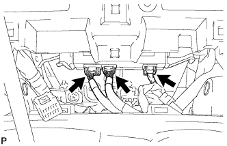
Disconnect each connector.
-
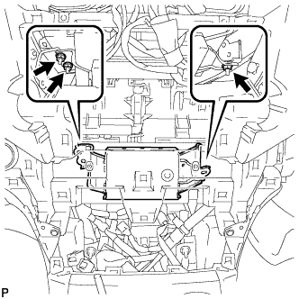
Remove the 3 nuts and multi-media interface ECU with bracket.
-
-
REMOVE NO. 1 MULTI-MEDIA INTERFACE BRACKET
-
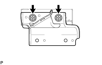
Remove the 2 screws and No. 1 multi-media interface bracket.
-
-
REMOVE NO. 2 MULTI-MEDIA INTERFACE BRACKET
-
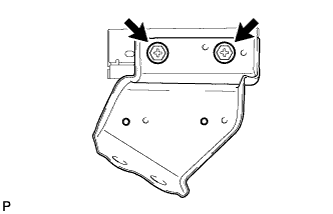
Remove the 2 screws and No. 2 multi-media interface bracket.
-
-
REMOVE MULTI-MEDIA INTERFACE ECU