RADIO ANTENNA CORD (for Glass Antenna Type) INSTALLATION
-
INSTALL NO. 2 ANTENNA CORD SUB-ASSEMBLY
Tech Tips
The double-sided tape and tape are not available as supply parts. If these tapes still have enough adhesion to secure the roof headlining and antenna cord, reuse the tapes. If the roof headlining has been replaced with a new one, or if the tape and/or the double-sided tape is no longer sticky, apply new tape following the procedures below.
-
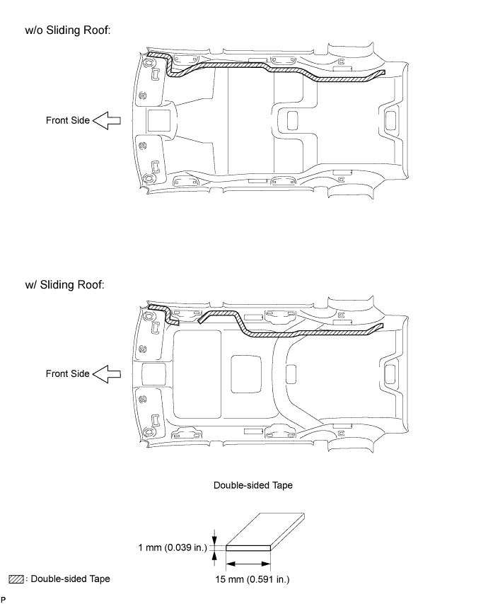
Apply new double-sided tape.
-
Remove the double-sided tape from the roof headlining assembly.
-
Peel off the appropriate amount of new double-sided tape. Be careful not to touch the adhesive surface.
-
Apply the double-sided tape to the roof headlining while aligning the tape with the markings on the roof headlining assembly.
-
Peel off the backing sheet from the double-sided tape.
-
-
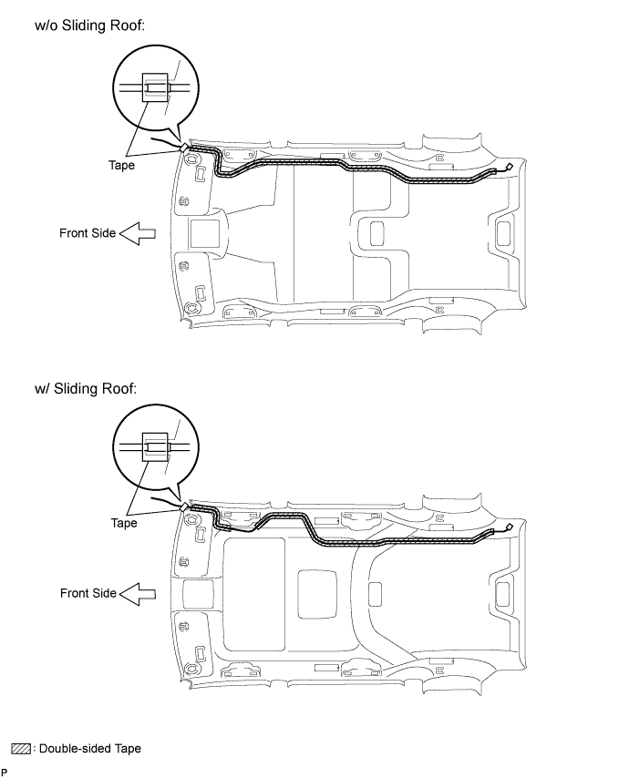
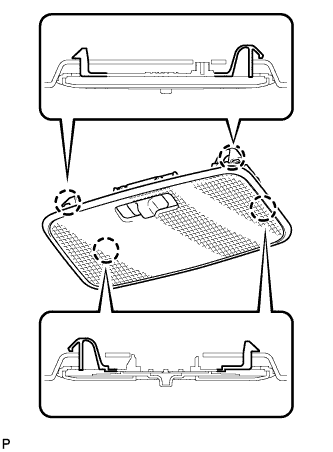
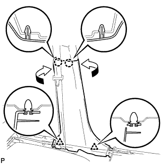
Install the antenna cord to the roof headlining assembly from the front of the vehicle.
-
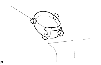
Put the strips of the tape back to the positions shown in the illustration in order to secure the antenna cord to the roof headlining assembly.
Tech Tips
For the right front corner of the roof headlining assembly, align the marking tape on the antenna cord with the protrusion of the roof headlining, and wrap tape around the antenna cord and roof headlining assembly once or twice to securely hold them.
-
-
INSTALL ROOF HEADLINING ASSEMBLY (w/o Sliding Roof)
-
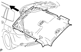
Pull the roof headlining assembly into the vehicle through the back door.
Note
Do not damage the roof headlining assembly or body interior.
-
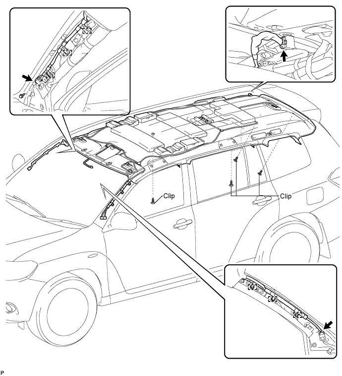
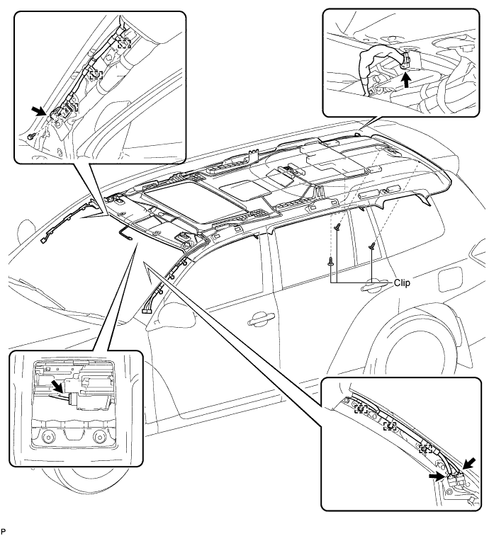
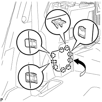
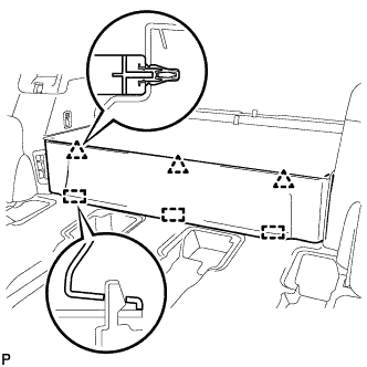
Install the 4 clips.
-
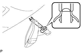
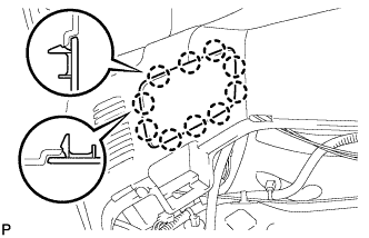
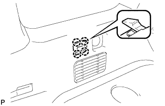
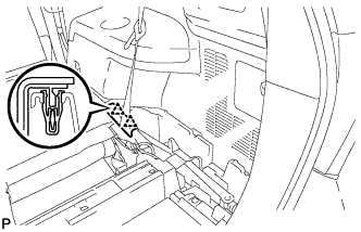
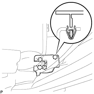
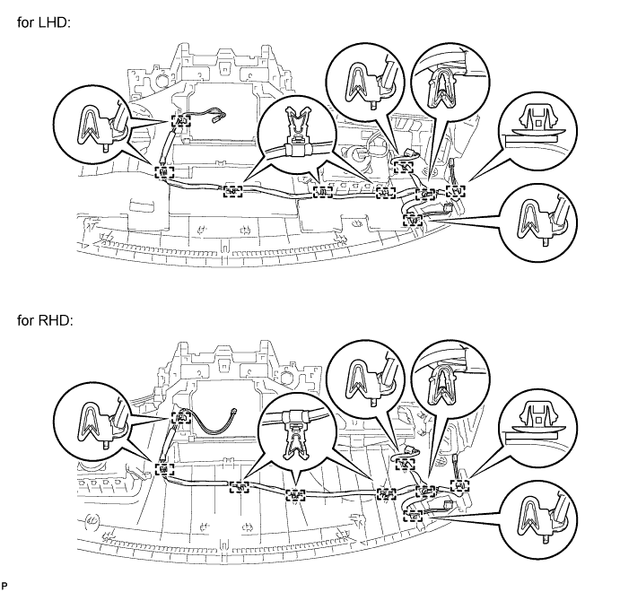
Connect the No. 2 antenna cord sub-assembly connector to the rear pillar RH.
-
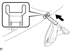
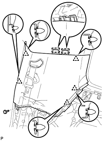
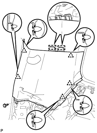
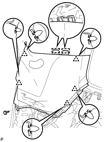
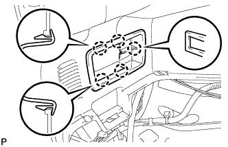
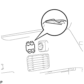
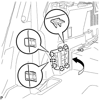
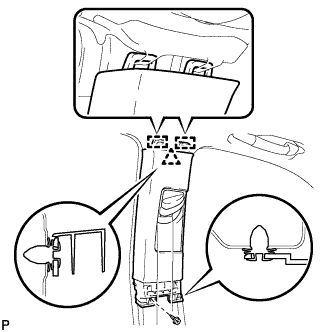
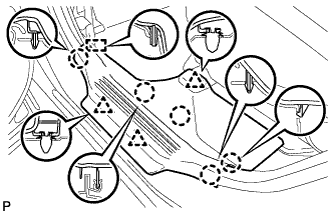
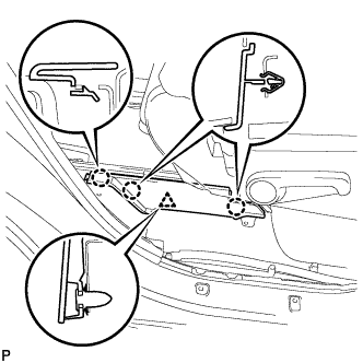
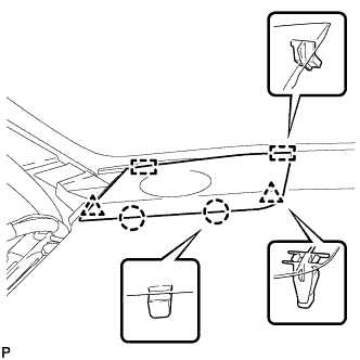
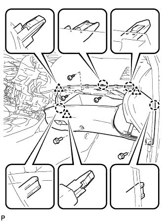
Connect the No. 2 antenna cord sub-assembly connectors and engage the 3 clamps to the front pillar RH.
-
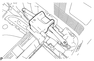
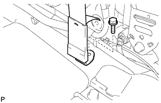
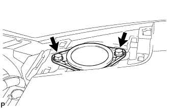
Install the No. 2 antenna cord sub-assembly to the front pillar RH with the bolt.
-
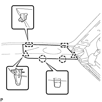
Connect the No. 1 roof wire connector and engage the 3 clamps to the front pillar LH.
Note
After installation, make sure that the back door weatherstrip does not interfere with the roof headlining assembly.
-
-
INSTALL ROOF HEADLINING ASSEMBLY (w/ Sliding Roof)
-
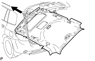
Pull the roof headlining assembly into the vehicle through the back door.
Note
Do not damage the roof headlining assembly or body interior.
-
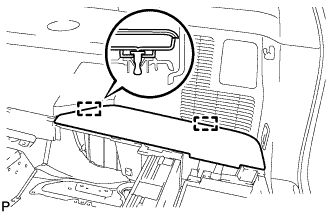
Install the 3 clips.
-
Connect the sliding roof drive gear connector.
-
Connect the No. 2 antenna cord sub-assembly connector to the rear pillar RH.
-
Connect the No. 2 antenna cord sub-assembly connector and engage the 3 clamps to the front pillar RH.
-
Install the No. 2 antenna cord sub-assembly to the front pillar RH with the bolt.
-
w/ Rear Seat Entertainment System:
-
Connect the No. 1 roof wire connector to the rear pillar LH.
-
-
Connect the No. 1 roof wire connectors and engage the 3 clamps to the front pillar LH.
Note
After installation, make sure that the back door weatherstrip does not interfere with the roof headlining assembly.
-
-
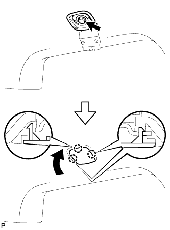
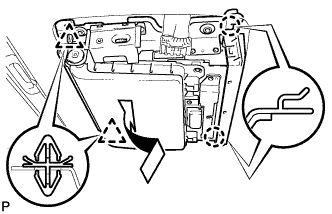
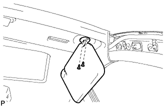
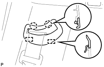
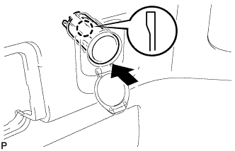
INSTALL VISOR HOLDER
-
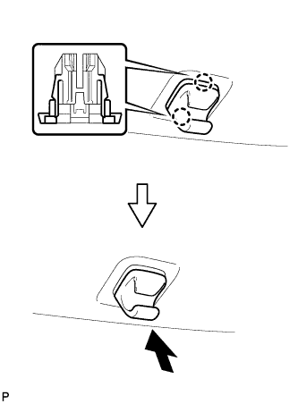
Engage the 2 claws.
-
Push in the visor holder as shown in the illustration.
Tech Tips
Use the same procedure for the RH side and the LH side.
-
-
INSTALL SUN ROOF OPENING TRIM MOULDING (w/ Sliding Roof)
-
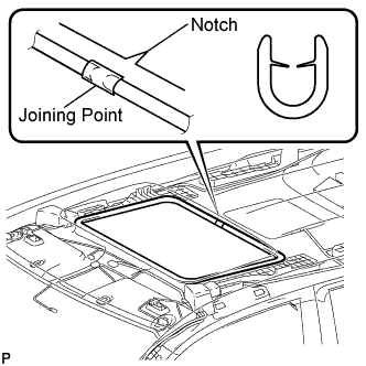
Align the joining point of the moulding with the notch of the roof headlining assembly, and install the sun roof opening trim moulding.
Note
After installation, check that the corners fit correctly.
-
-
INSTALL ROOF HEADLINING TRIM CLIP STOPPER
-
Install the roof headlining trim clip stopper with the bolt.
-
Engage the 3 claws.
Tech Tips
Use the same procedure for the RH side and the LH side.
-
-
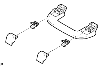
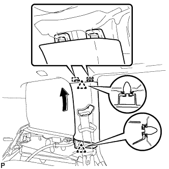
INSTALL ASSIST GRIP ASSEMBLY (w/ Sliding Roof)
-
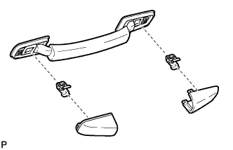
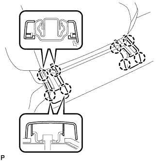
Assemble the assist grip assembly as shown in the illustration.
-
Install the assist grip assembly.
Tech Tips
Use the same procedure for the other 4 assist grips.
-
-
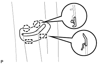
INSTALL REAR ASSIST GRIP SUB-ASSEMBLY (w/o Sliding Roof)
-
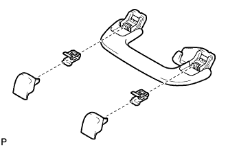
Assemble the rear assist grip sub-assembly as shown in the illustration.
-
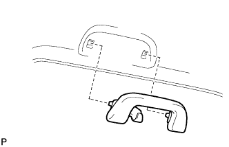
Install the rear assist grip sub-assembly.
Tech Tips
Use the same procedure for the other 4 assist grips.
-
-
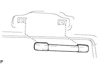
INSTALL FRONT ASSIST GRIP SUB-ASSEMBLY (w/o Sliding Roof)
-
Assemble the front assist grip sub-assembly as shown in the illustration.
-
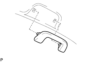
Install the front assist grip sub-assembly.
Tech Tips
Use the same procedure for the other 3 assist grips.
-
-
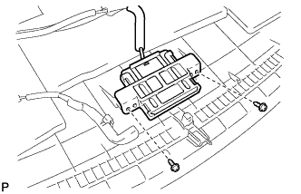
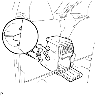
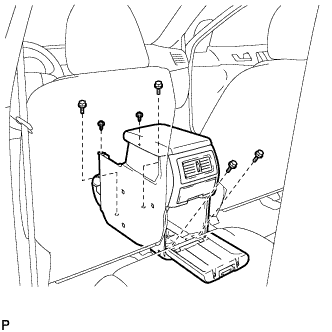
INSTALL TELEVISION DISPLAY ASSEMBLY (w/ Rear Seat Entertainment System)
-
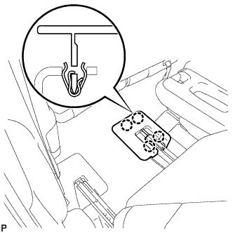
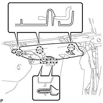
Engage the 2 claws and the 2 clips.
-
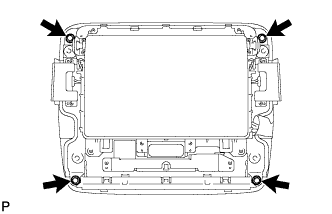
Install the television display with the 4 bolts.
Tech Tips
Tighten the bolts in the order shown in the illustration.
-
Connect the connector.
-
-
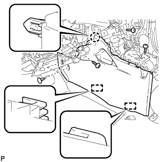
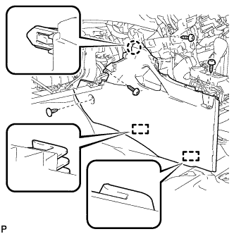
INSTALL TELEVISION BASE (w/ Rear Seat Entertainment System)
-
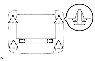
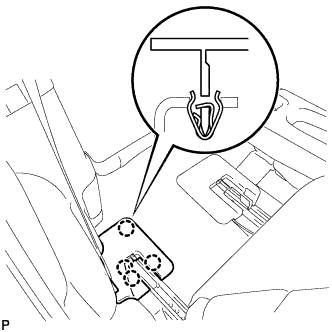
Engage the 2 guides and 4 clips and install the television base.
-
-
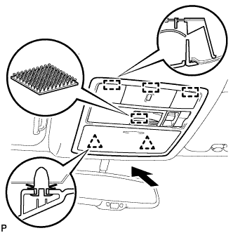
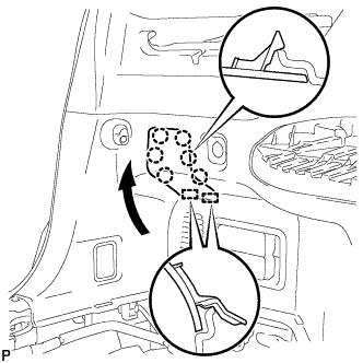
INSTALL NO. 2 ROOM LIGHT ASSEMBLY
-
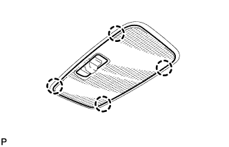
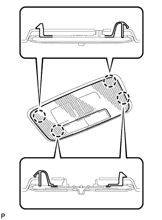
Engage the 4 claws and install the lens cover.
-
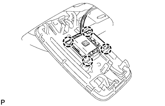
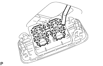
Engage the 4 claws and install the room light switch base to the No. 2 room light assembly.
-
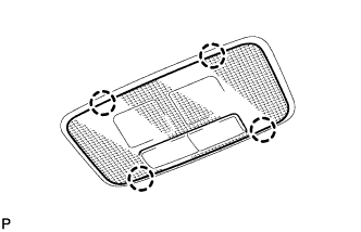
Engage the 4 claws and install the No. 2 room light assembly.
-
-
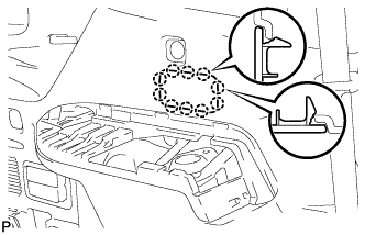
INSTALL NO. 1 ROOM LIGHT ASSEMBLY (for Standard)
-
Engage the 4 claws and install the lens cover.
-
Engage the 4 claws and install the room light switch base to the No. 1 room light assembly.
-
Engage the 4 claws and install the No. 1 room light assembly.
-
-
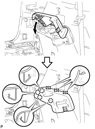
INSTALL NO. 1 ROOM LIGHT ASSEMBLY (for Independent Type)
-
Engage the 4 claws and install the lens cover.
-
Engage the 8 claws and install the room light switch base to the No. 1 room light assembly.
-
Engage the 4 claws and install the No. 1 room light assembly.
-
-
INSTALL INNER REAR VIEW MIRROR STAY HOLDER COVER (w/ EC Mirror)
-
Engage the 2 claws and install the inner rear view mirror stay holder cover.
-
Engage the 2 claws and install the inner rear view mirror stay holder cover as shown in the illustration.
-
-
INSTALL VISOR ASSEMBLY LH
-
Install the visor assembly LH with the 2 screws.
-
-
INSTALL VISOR BRACKET COVER (for LH Side)
-
Engage the 4 claws and install the visor bracket cover.
-
-
INSTALL VISOR ASSEMBLY RH
Tech Tips
Use the same procedure for the RH side and the LH side.
-
INSTALL VISOR BRACKET COVER (for RH Side)
Tech Tips
Use the same procedure for the RH side and the LH side.
-
INSTALL ROOF CONSOLE BOX ASSEMBLY
-
Connect the connector.
-
Engage the 3 guides, 2 clips, fastener, and install the roof console box assembly.
-
-
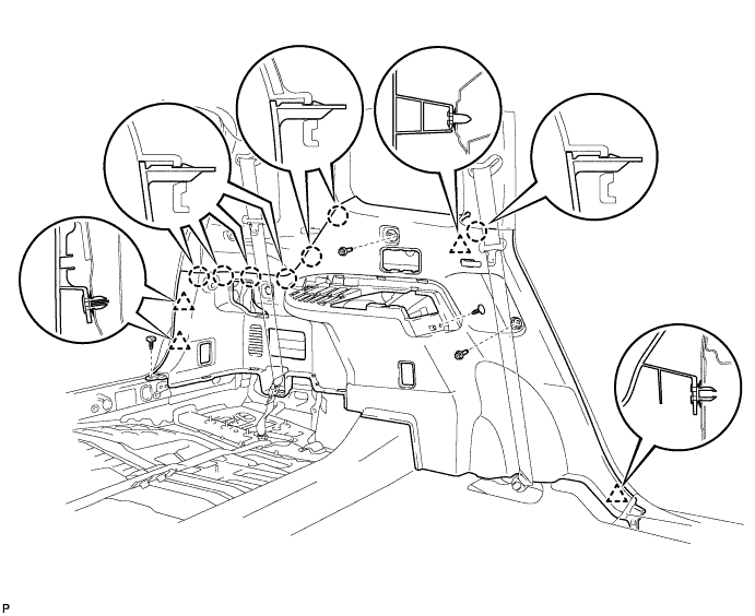
INSTALL ROOF SIDE INNER GARNISH ASSEMBLY LH (w/o Power Back Door)
-
w/ Rear No. 2 Seat:
-
Engage the 2 guides and 5 clips.
-
Install the roof side inner garnish assembly LH with the bolt.
-
Engage the 2 guides and the 2 claws, and install the No. 2 seat outer belt guide.
-
-
w/o Rear No. 2 Seat:
-
Engage the 2 guides and 5 clips.
-
Install the roof side inner garnish assembly LH with the bolt.
-
-
-
INSTALL ROOF SIDE INNER GARNISH ASSEMBLY LH (w/ Power Back Door)
-
w/ Rear No. 2 Seat:
-

Engage the 2 guides and 5 clips.
-
Install the roof side inner garnish assembly LH with the bolt.
-
Engage the 2 guides and the 2 claws, and install the No. 2 seat outer belt guide.
-
-
w/o Rear No. 2 Seat:
-
Engage the 2 guides and 5 clips.
-
Install the roof side inner garnish assembly LH with the bolt.
-
-
-
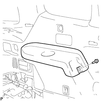
INSTALL QUARTER PILLAR GARNISH LH
-
Engage the 2 guides and the 2 clips, and install the quarter pillar garnish LH as shown in the illustration.
-
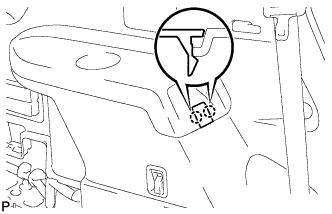
Engage the 2 guides and the 2 claws, and install the No. 1 seat outer belt guide.
-
-
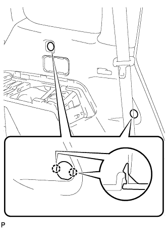
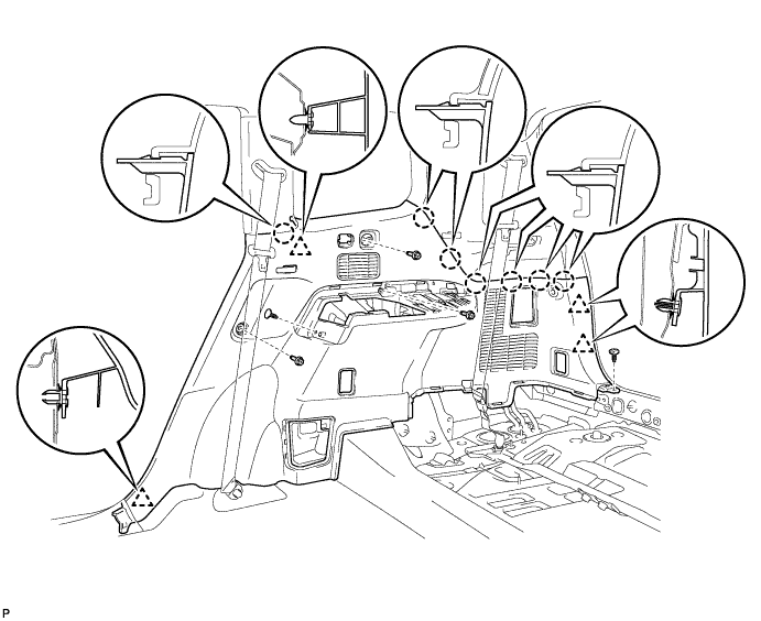
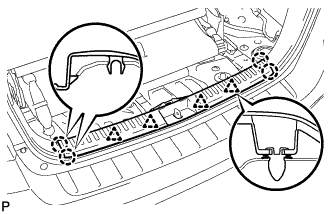
INSTALL DECK TRIM SIDE PANEL ASSEMBLY LH
-
Engage the 4 clips and the 7 claws.
-
Install the 2 clips.
-
Install the deck trim side panel assembly LH with the 2 bolts.
-
-
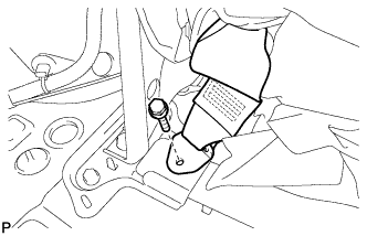
CONNECT REAR NO. 1 SEAT OUTER BELT ASSEMBLY LH
-
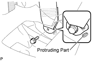
Connect the floor anchor end of the rear No. 1 seat outer belt assembly and install the bolt.
- Torque:
- 42 N*m { 428 kgf*cm, 31 ft.*lbf }
Note
Do not allow the anchor part of the rear No. 1 seat outer belt assembly to overlap the protruding part of the floor panel.
-
-
INSTALL FRONT DECK SIDE TRIM COVER LH
-
Engage the 4 claws and install the 2 front deck side trim covers LH.
-
-
INSTALL NO. 2 DECK SIDE TRIM HOOK
-
Install the No. 2 deck side trim hook with the screw.
-
-
INSTALL ROPE HOOK ASSEMBLY (for LH Side)
-
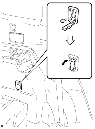
for Front Side:
-
Install the rope hook assembly with the bolt.
- Torque:
- 6.5 N*m { 66 kgf*cm, 58 in.*lbf }
-
Engage the 2 claws.
-
-
for Rear Side:
-
Install the rope hook assembly with the bolt.
- Torque:
- 6.5 N*m { 66 kgf*cm, 58 in.*lbf }
-
Engage the 2 claws.
-
-
-
INSTALL REAR DECK TRIM COVER (w/o Remote Folding Function)
-
Engage the 10 claws and install the rear deck trim cover.
-
-
INSTALL RECLINING REMOTE CONTROL LEVER BEZEL LH (w/ Remote Folding Function)
-
Engage the 5 claws and install the reclining remote control bezel LH.
-
-
INSTALL REAR POWER OUTLET SOCKET COVER
-
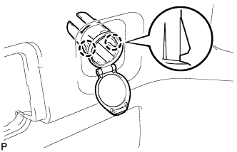
Engage the 2 claws and install the rear power outlet socket cover.
-
-
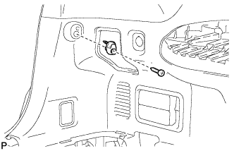
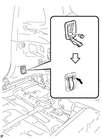
INSTALL REAR POWER POINT SOCKET ASSEMBLY
-
Engage the claw and install the rear power point socket assembly.
-
Connect the connector.
-
-
INSTALL REAR COMBINATION LIGHT SERVICE COVER LH
-
Engage the 2 guides and 6 claws, and install the rear combination light service cover LH.
-
-
INSTALL SIDE TRIM COVER LH
-
Engage the 10 claws and install the side trim cover LH.
-
-
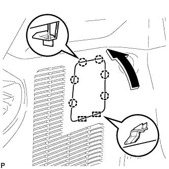
INSTALL DECK SIDE TRIM LH
-
Engage the 3 guides and 4 claws as shown in the illustration.
-
Install the deck side trim LH with the bolt.
-
-
INSTALL DECK SIDE TRIM COVER NO.2
-
Engage the 2 claws and install the deck side trim cover LH.
-
-
INSTALL ROOF SIDE INNER GARNISH ASSEMBLY RH (w/o Rear No. 2 Seat)
Tech Tips
Use the same procedure for the RH side and the LH side.
-
INSTALL ROOF SIDE INNER GARNISH ASSEMBLY RH (w/ Rear No. 2 Seat)
Tech Tips
Use the same procedure for the RH side and the LH side.
-
INSTALL QUARTER PILLAR GARNISH RH
Tech Tips
Use the same procedure for the RH side and the LH side.
-
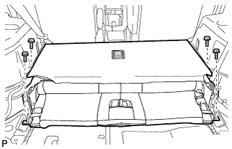
INSTALL DECK TRIM SIDE PANEL ASSEMBLY RH
-
Engage the 4 clips and the 7 claws.
-
Install the 2 clips.
-
Install the deck trim side panel assembly RH with the 3 bolts.
-
-
CONNECT REAR NO. 1 SEAT OUTER BELT ASSEMBLY RH
Tech Tips
Use the same procedure for the RH side and the LH side.
-
INSTALL FRONT DECK SIDE TRIM COVER RH
Tech Tips
Use the same procedure for the RH side and the LH side.
-
INSTALL NO. 1 LUGGAGE COMPARTMENT TRIM HOOK
Tech Tips
Use the same procedure for the No. 1 luggage compartment trim hook and the No. 2 deck side trim hook.
-
INSTALL ROPE HOOK ASSEMBLY (for RH Side)
Tech Tips
Use the same procedure for the RH side and the LH side.
-
INSTALL REAR COMBINATION LIGHT SERVICE COVER RH
-
Engage the 2 guides and 6 claws, and install the rear combination light service cover RH.
-
-
INSTALL REAR ROOM TEMPERATURE SENSOR (w/ Rear Automatic Air Conditioning System)
-
Connect the connector.
-
Engage the 4 claws and install the rear room temperature sensor.
-
-
INSTALL SIDE TRIM COVER RH (w/o Rear Automatic Air Conditioning System)
-
Engage the 4 claws, and install the side trim cover RH.
-
-
INSTALL DECK SIDE TRIM RH
Tech Tips
Use the same procedure for the RH side and the LH side.
-
INSTALL DECK SIDE TRIM COVER NO.1
Tech Tips
Use the same procedure for the RH side and the LH side.
-
INSTALL REAR SEAT SIDE GARNISH CAP (w/o Rear Air Conditioning System)
-
Engage the guide and the 8 claws, and install the rear seat side garnish cap.
-
-
INSTALL REAR SEAT SIDE GARNISH CAP (w/ Rear Air Conditioning System)
-
Engage the guide and the 6 claws.
-
Install the rear seat side garnish cap with the screw.
-
-
INSTALL REAR FLOOR FINISH PLATE
-
Engage the 4 clips and the 4 claws, and install the rear floor finish plate.
-
-
INSTALL REAR NO. 2 SEAT ASSEMBLY (w/ Rear No. 2 Seat)
-
Install the rear No. 2 seat assembly with the 4 bolts.
- Torque:
- 37 N*m { 377 kgf*cm, 27 ft.*lbf }
-
-
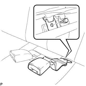
CONNECT REAR SEAT LAP TYPE BELT ASSEMBLY LH (w/ Rear No. 2 Seat)
-
Install the rear seat lap type belt assembly LH with the bolt.
- Torque:
- 42 N*m { 428 kgf*cm, 31 ft.*lbf }
Note
After installing the belt, check that it is not twisted.
-
-
CONNECT REAR SEAT LAP TYPE BELT ASSEMBLY RH (w/ Rear No. 2 Seat)
-
Install the rear seat lap type belt assembly RH with the bolt.
- Torque:
- 42 N*m { 428 kgf*cm, 31 ft.*lbf }
Note
After installing the belt, check that it is not twisted.
-
-
INSTALL REAR NO. 2 SEAT INNER BELT ASSEMBLY (w/ Rear No. 2 Seat)
-
Install the rear No. 2 seat inner belt assembly with the bolt.
- Torque:
- 42 N*m { 428 kgf*cm, 31 ft.*lbf }
Note
Do not allow the anchor part of the rear No. 2 seat inner belt assembly to overlap the protruding part of the rear No. 2 seat bracket.
Tech Tips
Use the same procedure for the RH side and LH side.
-
-
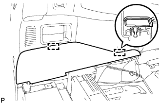
INSTALL REAR DECK FLOOR BOX (w/o Rear No. 2 Seat)
-
Install the rear deck floor box with the 2 nuts.
-
-
INSTALL DECK FLOOR BOARD ASSEMBLY (w/o Rear No. 2 Seat)
-
Install the 2 nuts and the deck floor board assembly.
-
Engage the 3 claws.
-
-
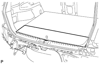
INSTALL REAR MAT
-
Install the rear mat.
-
-
INSTALL DECK FLOOR BOARD ASSEMBLY (w/ Rear No. 2 Seat)
-
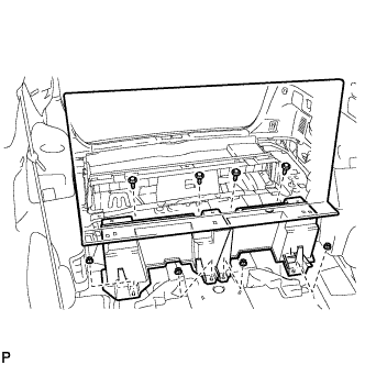
Install the rear deck floor board assembly with the 4 nuts and 4 bolts.
-
-
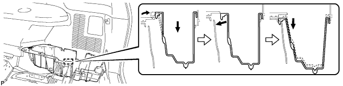
INSTALL DECK SIDE TRIM BOX LH
-
Install the deck side trim box LH as shown in the illustration.
-
Install the 2 deck side trim clips and the clip.
-
-
INSTALL REAR SEAT SIDE COVER LH (w/ Rear No. 2 Seat)
-
Engage the 2 clips and install the rear seat side cover LH.
-
-
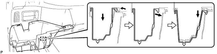
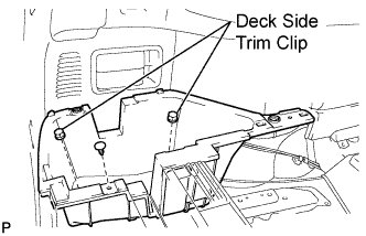
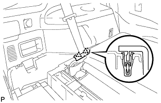
INSTALL DECK SIDE TRIM BOX RH
-
Install the deck side trim box RH as shown in the illustration.
-
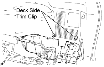
Install the 2 deck side trim clips and the clip.
-
-
INSTALL JACK CARRIER ASSEMBLY (for LHD)
-

Engage the 3 claws, and install the jack carrier assembly.
-
-
INSTALL JACK CARRIER ASSEMBLY (for RHD)
-
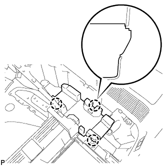
Engage the 3 claws, and install the jack carrier assembly.
-
-
INSTALL JACK ASSEMBLY (for LHD)
-
Install the jack assembly.
-
-
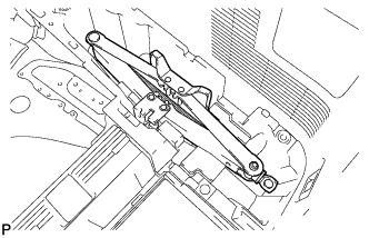
INSTALL JACK ASSEMBLY (for RHD)
-
Install the jack assembly.
-
-
INSTALL JACK CARRIER CUSHION (for LHD)
-
Install the jack carrier cushion.
-
-
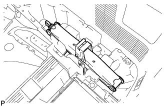
INSTALL JACK CARRIER CUSHION (for RHD)
-

Install the jack carrier cushion.
-
-
INSTALL JACK CARRIER SUPPORT
-
INSTALL REAR SEAT SIDE COVER RH (w/ Rear Air Conditioning System)
-
Engage the 2 clips and install the rear seat side cover RH.
-
-
INSTALL REAR NO. 1 FLOOR BOARD (w/o Rear Air Conditioning System)
-
Engage the 3 guides and 3 clips and install the rear No. 1 floor board.
-
-
INSTALL TONNEAU COVER ASSEMBLY (w/ Tonneau Cover)
-
Install the tonneau cover assembly.
-
-
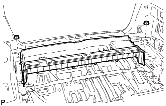
INSTALL NO. 2 DECK BOARD SUB-ASSEMBLY
-
Engage the 2 guides and install the No. 2 deck board sub-assembly.
-
-
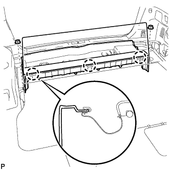
INSTALL NO. 3 DECK BOARD SUB-ASSEMBLY
-
Engage the 2 guides and install the No. 3 deck board sub-assembly.
-
-
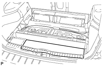
INSTALL DECK BOARD ASSEMBLY
-
Install the deck board sub-assembly.
-
-
INSTALL CENTER PILLAR GARNISH LH
-
Engage the 2 guides and the clip.
-
Install the center pillar garnish LH with the clip and screw.
-
-
CONNECT FRONT SEAT OUTER BELT ASSEMBLY LH
-
Install the floor end of the front seat outer belt assembly with the bolt.
- Torque:
- 42 N*m { 428 kgf*cm, 31 ft.*lbf }
-
Check if the ELR locks.
Note
The check should be performed with the outer belt assembly installed.
-
With the belt assembly installed, check that the belt locks when it is pulled out quickly.
-
-
-
INSTALL LOWER CENTER PILLAR GARNISH LH
-
Engage the 2 claws and the 2 clips, and install the lower center pillar garnish LH.
-
-
INSTALL REAR DOOR OPENING TRIM WEATHERSTRIP LH
-
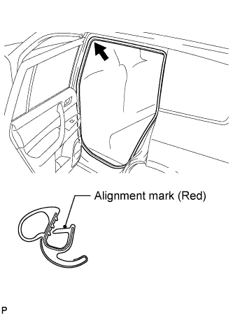
Align the alignment mark (red) on the weatherstrip with the protruding portion on the body indicated by the arrow in the illustration, and install the rear door opening trim weatherstrip LH.
Note
After installation, check that the corners fit correctly.
-
-
INSTALL REAR DOOR SCUFF PLATE LH
-
Engage the guide, 3 clips and 5 claws, and install the rear door scuff plate LH.
-
-
INSTALL CENTER PILLAR GARNISH RH
Tech Tips
Use the same procedure for the RH side and the LH side.
-
CONNECT FRONT SEAT OUTER BELT ASSEMBLY RH
Tech Tips
Use the same procedure for the RH side and the LH side.
-
INSTALL LOWER CENTER PILLAR GARNISH RH
Tech Tips
Use the same procedure for the RH side and the LH side.
-
INSTALL REAR DOOR OPENING TRIM WEATHERSTRIP RH
-
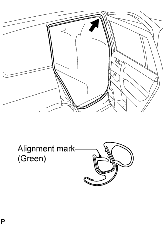
Align the alignment mark (green) on the weatherstrip with the protruding portion on the body indicated by the arrow in the illustration, and install the rear door opening trim weatherstrip RH.
Note
After installation, check that the corners fit correctly.
-
-
INSTALL REAR DOOR SCUFF PLATE RH
Tech Tips
Use the same procedure for the RH side and the LH side.
-
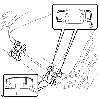
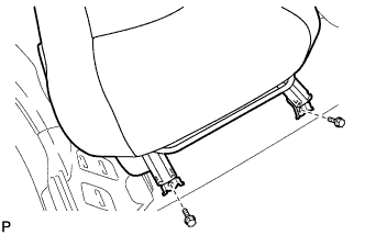
INSTALL REAR NO. 1 SEAT ASSEMBLY LH
-
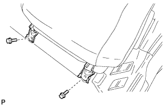
Temporarily install the 2 bolts on the front side of the seat.
-
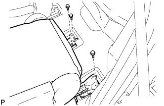
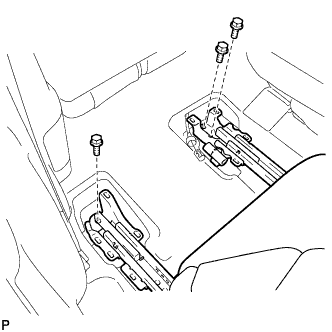
Temporarily install the 3 bolts on the rear side of the seat.
-
Install the rear No. 1 seat assembly with the 5 bolts.
- Torque:
- 37 N*m { 377 kgf*cm, 27 ft.*lbf }
-
-
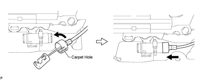
CONNECT REAR NO. 1 SEAT LOCK CABLE ASSEMBLY LH (w/ Remote Folding Function)
-
Remove the rear seat reclining control cable from the carpet hole.
-
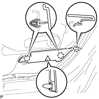
Connect the rear seat reclining control cable as shown in the illustration.
-
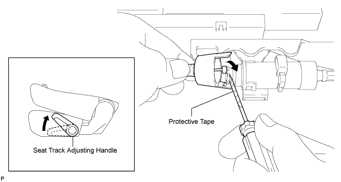
Connect the rear No. 1 seat lock cable assembly as shown in the illustration.
-
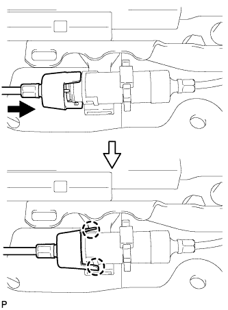
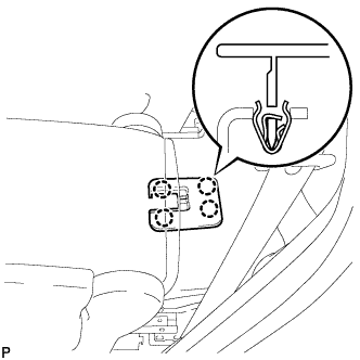
Engage the 2 claws and connect the rear No. 1 seat lock cable assembly as shown in the illustration.
-
Return the seatback to the upright position.
-
Pull up the adjuster's lock piece to lock it as shown in the illustration.
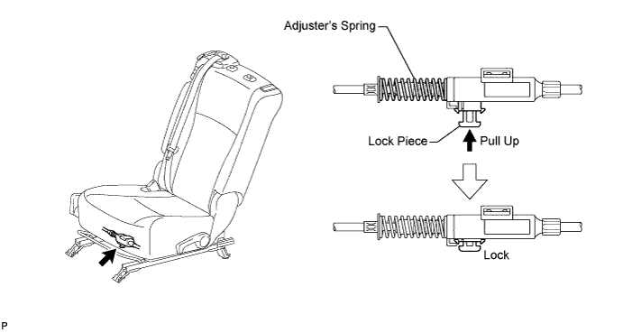
Note
When pressing the lock piece, make sure the adjuster's spring is not compress.
-
-
INSPECT REAR SEAT SLIDE ADJUSTER LOCK (for LH Side)
-
Check that the left and right adjusters lock simultaneously when sliding the seat.
-
If the left and right adjusters do not lock simultaneously, adjust by loosening the bolts securing the seat.
-
-
INSTALL REAR SEAT LEG SIDE COVER LH
-
Engage the clip.
-
Engage the 3 claws and install the rear seat leg side cover.
-
-
INSTALL REAR INNER TRACK BRACKET COVER LH
-
Engage the 4 claws and install the rear inner track bracket cover.
-
-
INSTALL REAR OUTER TRACK BRACKET COVER LH
-
Engage the 4 claws and install the rear outer track bracket cover.
-
-
INSTALL REAR SEAT TRACK BRACKET COVER LH
-
Engage the 8 claws and install the 2 rear seat track bracket covers.
-
-
INSTALL REAR SEAT HEADREST ASSEMBLY (for LH Side)
-
INSTALL REAR CENTER SEAT ASSEMBLY
-
INSTALL REAR NO. 1 SEAT ASSEMBLY RH
-
Temporarily install the 2 bolts on the front side of the seat.
-
Temporarily Install the 3 bolts on the rear side of the seat.
-
Install the rear No. 1 seat assembly with the 5 bolts.
- Torque:
- 37 N*m { 377 kgf*cm, 27 ft.*lbf }
-
-
CONNECT REAR NO. 1 SEAT LOCK CABLE ASSEMBLY RH (w/ Remote Folding Function)
Tech Tips
Use the same procedure for the RH side and the LH side.
-
INSPECT REAR SEAT SLIDE ADJUSTER LOCK (for RH Side)
-
Check that the left and right adjusters lock simultaneously when sliding the seat.
-
If the left and right adjusters do not lock simultaneously, adjust by loosening the bolts securing the seat.
-
-
INSTALL REAR SEAT LEG SIDE COVER RH
-
Engage the clip.
-
Engage the 3 claws and install the rear seat leg side cover.
-
-
INSTALL REAR INNER TRACK BRACKET COVER RH
-
Engage the 4 claws and install the rear inner track bracket cover.
-
-
INSTALL REAR OUTER TRACK BRACKET COVER RH
-
Engage the 4 claws and install the rear outer track bracket cover.
-
-
INSTALL REAR SEAT TRACK BRACKET COVER RH
-
Engage the 8 claws and install the 2 seat track bracket covers.
-
-
INSTALL REAR SEAT HEADREST ASSEMBLY (for RH Side)
-
INSTALL ANTENNA CORD SUB-ASSEMBLY
-
Engage the 9 clamps and install the antenna cord sub-assembly.
-
-
INSTALL NAVIGATION ANTENNA ASSEMBLY (w/ Navigation System)
-
Install the navigation antenna with the 2 screws.
-
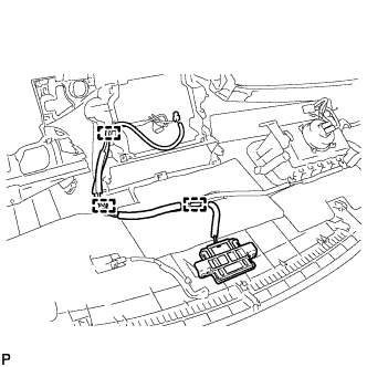
Engage the 3 clamps and install the navigation antenna assembly.
-
-
INSTALL CENTER HEATER TO REGISTER SUB DUCT
-
Install the center heater to register sub duct with the 2 screws <F>.
-
-
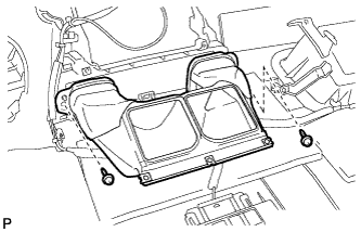
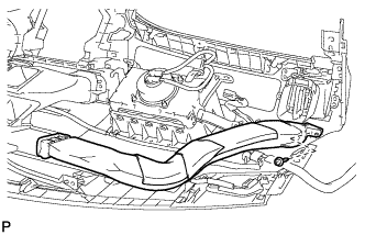
INSTALL DEFROSTER NOZZLE ASSEMBLY
-
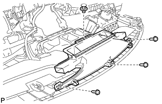
Install the defroster nozzle assembly with the 3 screws <F> and clip.
-
-
INSTALL SIDE NO. 2 DEFROSTER NOZZLE DUCT
-
Install the side No. 2 defroster nozzle duct with the screw <F>.
-
-
INSTALL SIDE NO. 1 DEFROSTER NOZZLE DUCT
-
Install the side No. 1 defroster nozzle duct with the screw <F>.
-
-
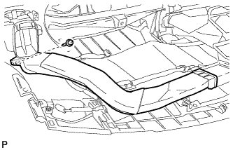
INSTALL NO. 4 HEATER TO REGISTER DUCT
-
Install the No. 4 heater to register duct with the 3 screws <F>.
-
-
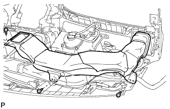
INSTALL NO. 1 HEATER TO REGISTER DUCT
-
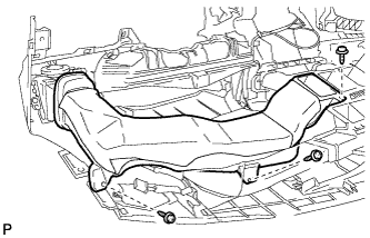
Install the No. 1 heater to register duct with the 3 screws <F>.
-
-
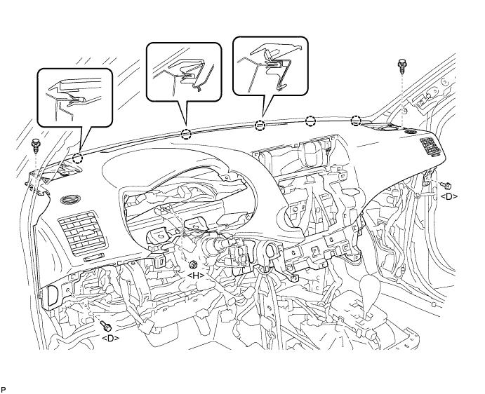
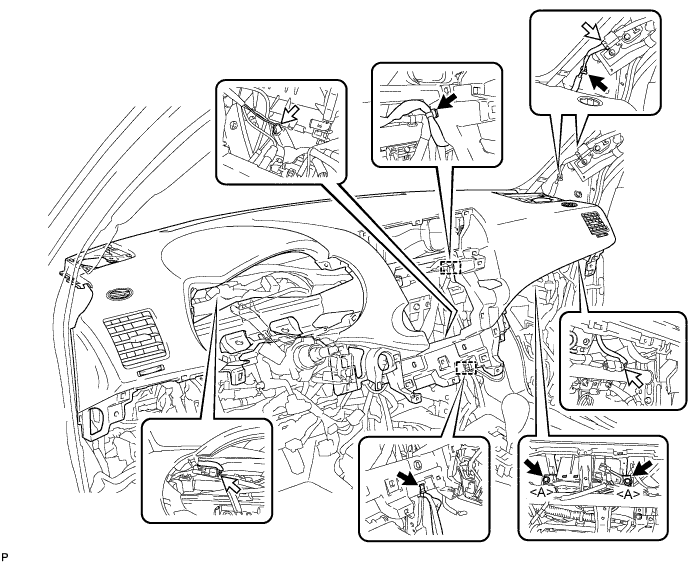
INSTALL INSTRUMENT PANEL SAFETY PAD ASSEMBLY
-
Engage the 5 claws.
Note
Do not allow the wire harness to get caught in the claws.
-
Install the 2 bolts <D> and nut <H>.
-
Install the 2 clips.
-
Engage each clamp.
-
Install the 2 passenger airbag bolts <A>.
- Torque:
- 20 N*m { 204 kgf*cm, 15 ft.*lbf }
-
Connect each connector and install the instrument panel safety pad assembly.
-
-
CONNECT INSTRUMENT PANEL WIRE ASSEMBLY
-
Check that the ignition switch is off.
-
Check that the battery negative (-) terminal is disconnected.
CAUTION:
Wait for at least 90 seconds after disconnecting the cable to prevent airbag deployment.
-
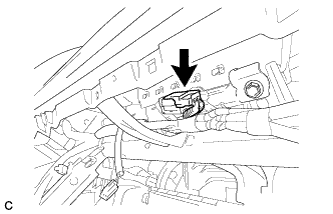
Connect the connector.
-
-
INSTALL FRONT NO. 2 SPEAKER ASSEMBLY (for LH Side)
-
Connect the connector.
-
Install the front No. 2 speaker assembly with the 2 bolts.
-
-
INSTALL NO. 1 INSTRUMENT PANEL SPEAKER PANEL SUB-ASSEMBLY
-
Engage the 2 guides.
-
Engage the 2 claws and 2 clips, and install the No. 1 instrument panel speaker panel sub-assembly.
-
-
INSTALL FRONT NO. 2 SPEAKER ASSEMBLY (for RH Side)
Tech Tips
Use the same procedure for the RH side and the LH side.
-
INSTALL NO. 2 INSTRUMENT PANEL SPEAKER PANEL SUB-ASSEMBLY
-
Engage the 2 guides.
-
Engage the 2 claws and 2 clips, and install the No. 2 instrument panel speaker panel sub-assembly.
-
-
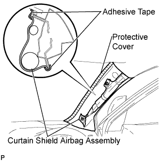
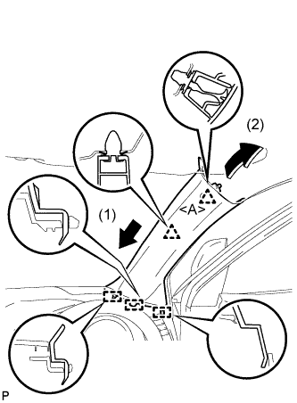
INSTALL FRONT PILLAR GARNISH LH
-
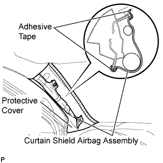
Remove the protective cover.
-
Install a new clip <A> on the front pillar garnish LH.
-
Engage the 3 guides and 2 clips, then install the front pillar garnish LH.
-
-
INSTALL FRONT DOOR OPENING TRIM WEATHERSTRIP LH
-
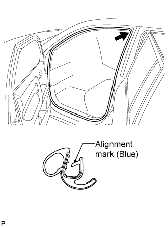
Align the alignment mark (blue) on the weatherstrip with the protruding portion on the body indicated by the arrow in the illustration, and install the front door opening trim weatherstrip LH.
Note
After installation, check that the corners fit correctly.
-
-
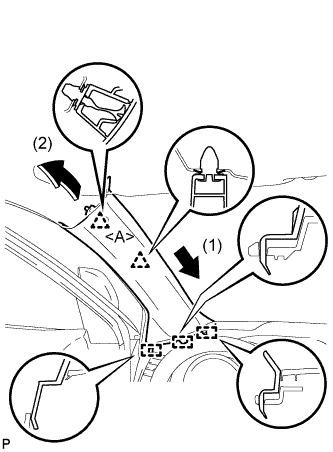
INSTALL FRONT PILLAR GARNISH RH
-
Remove the protective cover.
-
Install a new clip <A> on the front pillar garnish RH.
-
Engage the 3 guides and 2 clips, then install the front pillar garnish RH.
-
-
INSTALL FRONT DOOR OPENING TRIM WEATHERSTRIP RH
-
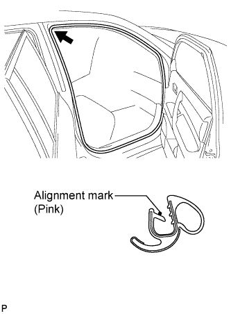
Align the alignment mark (pink) on the weatherstrip with the protruding portion on the body indicated by the arrow in the illustration, and install the front door opening trim weatherstrip RH.
Note
After installation, check that the corners fit correctly.
-
-
INSTALL ENGINE SWITCH (w/ Smart Entry and Start System)
-
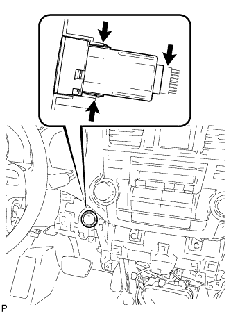
Engage the 2 claws to install the switch.
-
Connect the switch connector.
-
-
INSTALL FRONT NO. 2 CONSOLE BOX INSERT (for LHD)
-
Engage the claw and 2 guides.
-
Install the front No. 2 console box insert with the 3 screws <F> and clip.
-
-
INSTALL FRONT NO. 2 CONSOLE BOX INSERT (for RHD)
-
Engage the claw and 2 guides.
-
Install the front No. 2 console box insert with the 3 screws <F> and clip.
-
-
INSTALL FRONT NO. 1 CONSOLE BOX INSERT (for LHD)
-
Engage the claw and 2 guides.
-
Install the front No. 1 console box insert with the 3 screws <F> and 2 clips.
-
-
INSTALL FRONT NO. 1 CONSOLE BOX INSERT (for RHD)
-
Engage the claw and 2 guides.
-
Install the front No. 1 console box insert with the 3 screws <F> and clip.
-
-
INSTALL CONSOLE BOX ASSEMBLY (w/o Rear Air Conditioning System)
-
Engage the 6 claws.
-
Install the console box assembly with the 4 bolts and 2 screws.
-
-
INSTALL CONSOLE BOX ASSEMBLY (w/ Rear Air Conditioning System)
-
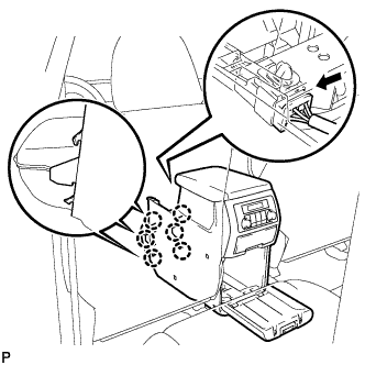
Engage the 6 claws.
-
Connect the connector.
-
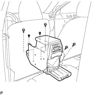
Install the console box assembly with the 4 bolts and 2 screws.
-
-
INSTALL LOWER REAR CONSOLE BOX
-
Install the lower rear console box.
-
-
INSTALL NO. 2 CONSOLE BOX DUCT (w/o Rear Air Conditioning System)
-
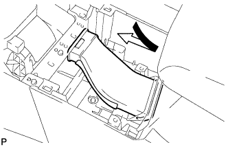
Install the No. 2 console box duct as shown in the illustration.
-
-
INSTALL UPPER CONSOLE PANEL SUB-ASSEMBLY
-
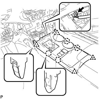
Connect the connector.
-
Engage the 4 claws and 4 clips, and install the upper console panel sub-assembly.
-
-
INSTALL LOWER INSTRUMENT PANEL SUB-ASSEMBLY
-
Connect each connector and clamp.
-
Engage the 4 claws and 3 clips.
-
Install the lower instrument panel sub-assembly with the 2 bolts <B> and 3 screws <F>.
-
-
INSTALL NO. 2 INSTRUMENT PANEL UNDER COVER SUB-ASSEMBLY
-
Engage the 2 guides.
-
Engage the 3 claws and install the No. 2 instrument panel under cover sub-assembly.
-
-
INSTALL LOWER INSTRUMENT PANEL FINISH PANEL SUB-ASSEMBLY (for Manual Air Conditioning System)
-

Connect the hood lock control cable assembly.
-
Connect each connector.
-
Engage the 3 claws and 10 clips.
-
Install the lower instrument panel finish panel sub-assembly with the 2 bolts <B>.
-
-
INSTALL LOWER INSTRUMENT PANEL FINISH PANEL SUB-ASSEMBLY (for Automatic Air Conditioning System)
-

Connect the hood lock control cable assembly.
-
Connect each connector and the aspirator duct.
-

Engage the 3 claws and 10 clips.
-
Install the lower instrument panel finish panel sub-assembly with the 2 bolts <B>.
-
-
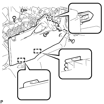
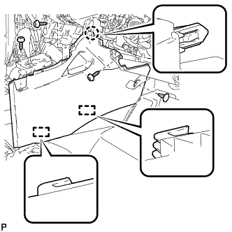
INSTALL COWL SIDE TRIM SUB-ASSEMBLY LH
-

Engage the claw and clip, install the cowl side trim sub-assembly LH.
-
Install the clip.
-
-
INSTALL FRONT DOOR SCUFF PLATE LH
-

Engage the guide and the 8 claws, and install the front door scuff plate LH.
-
-
INSTALL COWL SIDE TRIM SUB-ASSEMBLY RH
Tech Tips
Use the same procedure for the RH side and the LH side.
-
INSTALL FRONT DOOR SCUFF PLATE RH
Tech Tips
Use the same procedure for the RH side and the LH side.
-
INSTALL RADIO RECEIVER ASSEMBLY WITH BRACKET (w/o Navigation System)
-
Connect each connector.
-
Engage the 4 clips.
-
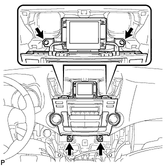
Install the radio receiver assembly with bracket with the 4 bolts.
-
-
INSTALL NAVIGATION RECEIVER ASSEMBLY WITH BRACKET (w/ Navigation System)
-
Connect each connector.
-
Engage the 4 clips.
-
Install the navigation receiver assembly with bracket with the 4 bolts.
-
-
INSTALL INTEGRATION CONTROL AND PANEL ASSEMBLY WITH BRACKET (w/o Radio Receiver)
-
Connect each connector.
-
Engage the 4 clips.
-
Install the integration control and panel assembly with bracket with the 4 bolts <D>.
-
-
INSTALL HEATER CONTROL AND ACCESSORY ASSEMBLY (for Manual Air Conditioning System)
-
Connect the connector.
-

Engage the 4 clips and install the heater control and accessory assembly.
-
-
INSTALL AIR CONDITIONING CONTROL ASSEMBLY (for Automatic Air Conditioning System)
-
Connect the connector.
-
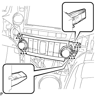
Engage the 4 clips and install the air conditioning control assembly.
-
-
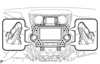
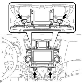
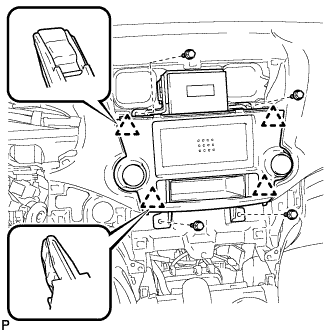
INSTALL CENTER INSTRUMENT CLUSTER FINISH PANEL ASSEMBLY (w/o Smart Entry and Start System)
-

Apply protective tape to the areas shown in the illustration.
-
Connect each connector.
-
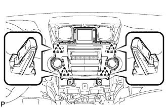
Engage the 10 claws and 8 clips, and install the center instrument cluster finish panel assembly.
Note
Do not the damage the instrument panel safety pad assembly and lower instrument panel finish panel sub-assembly.
-
-
INSTALL CENTER INSTRUMENT CLUSTER FINISH PANEL ASSEMBLY (w/ Smart Entry and Start System)
-
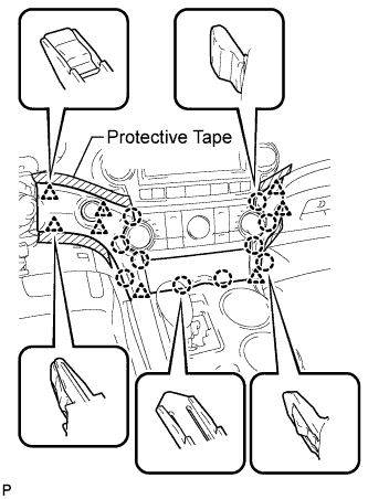
Apply protective tape to the areas shown in the illustration.
-
Connect each connector.
-
Engage the 10 claws and 8 clips, and install the center instrument cluster finish panel assembly.
Note
Do not the damage the instrument panel safety pad assembly and lower instrument panel finish panel sub-assembly.
-
-
INSTALL CENTER INSTRUMENT PANEL REGISTER ASSEMBLY
-
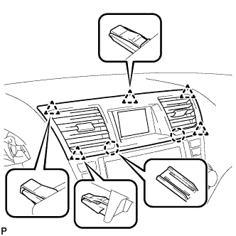
Engage the 2 claws and 5 clips, and install the center instrument panel register assembly.
-
-
INSTALL COMBINATION METER ASSEMBLY
-
Connect the connector.
-
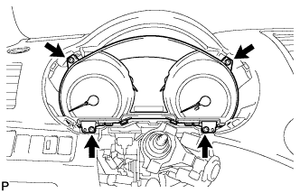
Install the combination meter assembly with the 4 screws <F>.
-
-
INSTALL INSTRUMENT CLUSTER FINISH PANEL ASSEMBLY
-
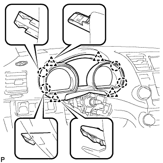
Engage the 4 claws and 4 clips, and install the instrument cluster finish panel assembly.
-
-
POSITION FRONT WHEELS STRAIGHT AHEAD
-
INSTALL TURN SIGNAL SWITCH ASSEMBLY WITH SPIRAL CABLE SUB-ASSEMBLY
-
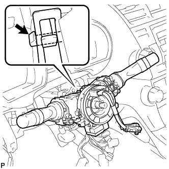
Using pliers, engage the claw. Install the turn signal switch assembly with spiral cable sub-assembly to the steering column assembly.
-
Connect the connectors to the turn signal switch assembly with spiral cable sub-assembly.
-
-
INSTALL STEERING COLUMN COVER
-
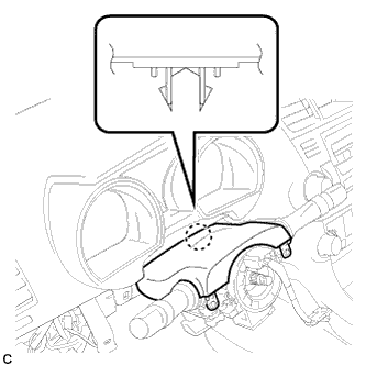
Engage the claw to install the upper steering column cover.
-
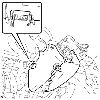
Engage the 2 claws to install the lower steering column cover.
-
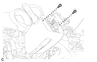
Install the 2 screws.
- Torque:
- 2.0 N*m { 20 kgf*cm, 18 in.*lbf }
-
-
ADJUST SPIRAL CABLE SUB-ASSEMBLY
-
Check that the ignition switch is off.
-
Check that the battery negative (-) cable is disconnected.
CAUTION:
Wait for at least 90 seconds after disconnecting the cable to prevent airbag deployment.
-
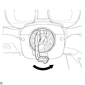
Rotate the spiral cable counterclockwise slowly by hand until it stops.
Note
Do not turn the spiral cable using the airbag wire harness.
-
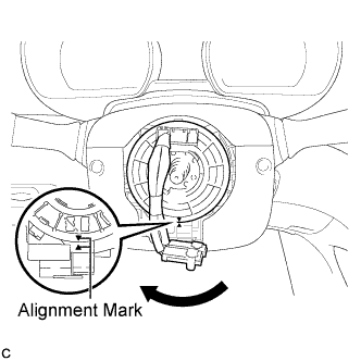
Rotate the spiral cable clockwise approximately 2.5 turns to align the marks.
Note
Do not turn the spiral cable using the airbag wire harness.
Tech Tips
The spiral cable will rotate approximately 2.5 turns to both the left and right from the center.
-
-
INSTALL STEERING WHEEL ASSEMBLY
-
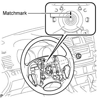
Align the matchmarks on the steering wheel assembly and steering main shaft.
-
Install the steering wheel assembly set nut.
- Torque:
- 50 N*m { 510 kgf*cm, 37 ft.*lbf }
-
Connect the connectors to the spiral cable sub-assembly.
-
-
INSPECT STEERING WHEEL CENTER POINT
-
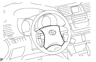
INSTALL STEERING PAD
-
Check that the ignition switch is off.
-
Check that the battery negative (-) terminal is disconnected.
CAUTION:
Wait for at least 90 seconds after disconnecting the cable to prevent airbag deployment.
-
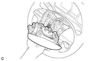
Support the steering pad with one hand as shown in the illustration.
-
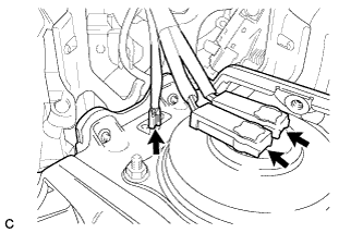
Connect the 2 airbag connectors to the steering pad.
Note
When handling the airbag connector, take care not to damage the airbag wire harness.
-
Connect the horn connector to the steering pad.
-
Confirm that the circumference groove of the "TORX" screw fits in the screw case, and place the steering pad onto the steering wheel assembly.
-
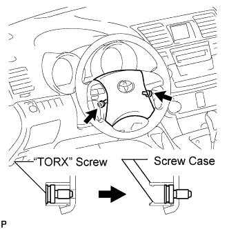
Using a "TORX" socket wrench (T30), tighten the 2 "TORX" screws.
- Torque:
- 8.8 N*m { 90 kgf*cm, 78 in.*lbf }
-
-
INSTALL LOWER NO. 3 STEERING WHEEL COVER
-
Install the lower No. 3 steering wheel cover with the claw.
-
-
INSTALL LOWER NO. 2 STEERING WHEEL COVER
-
Install the lower No. 2 steering wheel cover with the claw.
-
-
CONNECT CABLE TO NEGATIVE BATTERY TERMINAL
Note
When disconnecting the cable, some systems need to be initialized after the cable is reconnected Click here.
-
INSPECT STEERING PAD
-
With the steering pad installed on the vehicle, perform a visual check. If there are any defects as mentioned below, replace the steering pad with a new one:
-
Cuts, minute cracks or marked discoloration on the steering pad top surface or grooves.
-
-
Make sure that the horn sounds.
Tech Tips
If the horn does not sound, inspect the horn system Click here.
-
-
INSPECT SRS WARNING LIGHT