STEERING PAD SWITCH INSPECTION
-
INSPECT STEERING PAD SWITCH ASSEMBLY
-
Disconnect the steering pad switch assembly connector.
-
Measure the resistance according to the values in the table below.
Standard Resistance Tester connection Condition Specified condition AU1 - EAU No switch is pushed 95 to 105 kΩ AU1 - EAU Seek+ switch: pushed Below 2.5 Ω AU1 - EAU Seek- switch: pushed 312 to 345 Ω AU1 - EAU Volume+ switch: pushed 950 to 1050 Ω AU1 - EAU Volume- switch: pushed 2954 to 3265 Ω AU2 - EAU No switch is pushed 95 to 105 kΩ AU2 - EAU MODE switch: pushed Below 2.5 Ω AU2 - EAU Voice switch: pushed*1 2954 to 3265 Ω AU2 - EAU On hook switch: pushed*1 312 to 345 Ω AU2 - EAU Off hook switch: pushed*1 950 to 1050 Ω
-
*1: w/ Telephone Microphone Assembly
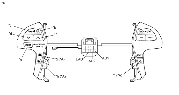
Text in Illustration *A w/ Telephone Microphone Assembly *a Component without harness connected
(Steering Pad Switch Assembly)
*b Volume+ *c Volume- *d Seek- *e MODE *f Seek+ *g On hook *h Off hook *i Voice If the result is not as specified, replace the steering pad switch assembly.
-
-