| DTC Code | DTC Name |
|---|---|
| Microphone Circuit between Microphone and Radio Receiver |
DESCRIPTION
This circuit sends the voice signal from the telephone microphone assembly to the radio receiver.
It also supplies power from the radio receiver to the telephone microphone assembly.
INSPECTION PROCEDURE
PROCEDURE
- Click here
INSPECT RADIO RECEIVER
-
Disconnect the radio receiver connector.
-
Measure the voltage according to the value(s) in the table below.
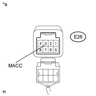
Standard Voltage Tester Connection Condition Specified Condition E26-3 (MACC) - Body ground Ignition switch ON 4 to 6 V Table 1. Text in Illustration *a Component without harness connected
(Radio Receiver)
- OKClick here
- NGClick here
-
- Click here
CHECK HARNESS AND CONNECTOR (TELEPHONE MICROPHONE ASSEMBLY - RADIO RECEIVER)
-
Disconnect the telephone microphone assembly and radio receiver connectors.
-
Measure the resistance according to the value(s) in the table below.
Standard Resistance Tester Connection Condition Specified Condition Q15-4 (SNS2) - E26-1 (SNS2) Always Below 1 Ω Q15-3 (MIC+) - E26-2 (MIN+) Always Below 1 Ω Q15-5 (MIC-) - E26-5 (MIN-) Always Below 1 Ω Q15-1 (MACC) - E26-3 (MACC) Always Below 1 Ω Q15-4 (SNS2) - Body ground Always 10 kΩ or higher Q15-3 (MIC+) - Body ground Always 10 kΩ or higher Q15-5 (MIC-) - Body ground Always 10 kΩ or higher Q15-1 (MACC) - Body ground Always 10 kΩ or higher E26-6 (SGND) - Body ground Always 10 kΩ or higher
- OKClick here
- NGClick here
-
- Click here
INSPECT TELEPHONE MICROPHONE ASSEMBLY
-
Measure the resistance according to the value(s) in the table below.
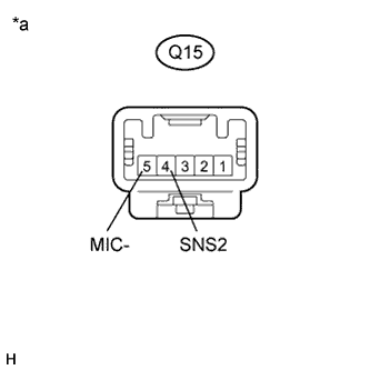
Standard Resistance Tester Connection Condition Specified Condition Q15-4 (SNS2) - Q15-5 (MIC-) Always Below 1 Ω Table 2. Text in Illustration *a Component without harness connected
(Telephone Microphone Assembly)
- OKClick here
- NGClick here
-
- Click here
INSPECT TELEPHONE MICROPHONE ASSEMBLY
-
Reconnect the radio receiver connector.
-
Reconnect the telephone microphone assembly connector.
-
Turn the ignition switch to ACC.
-
Connect an oscilloscope to terminals 3 (MIC+) and 5 (MIC-) of the telephone microphone assembly connector.
-
Check the waveform of the telephone microphone assembly using an oscilloscope.
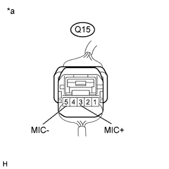
Result Result Proceed to A waveform synchronized with the voice input to the telephone microphone assembly is output A A waveform synchronized with the voice input to the telephone microphone is not output B Table 3. Text in Illustration *a Component with harness connected
(Telephone Microphone Assembly)
-
- Click here
PROCEED TO NEXT SUSPECTED AREA SHOWN IN PROBLEM SYMPTOMS TABLEClick here
- Click here
REPLACE RADIO RECEIVERClick here
- Click here
REPAIR OR REPLACE HARNESS OR CONNECTOR
- Click here
REPLACE TELEPHONE MICROPHONE ASSEMBLYClick here