AUDIO AND VISUAL SYSTEM Sound Signal Circuit between Multi-media Interface ECU and Stereo Jack Adapter
DESCRIPTION
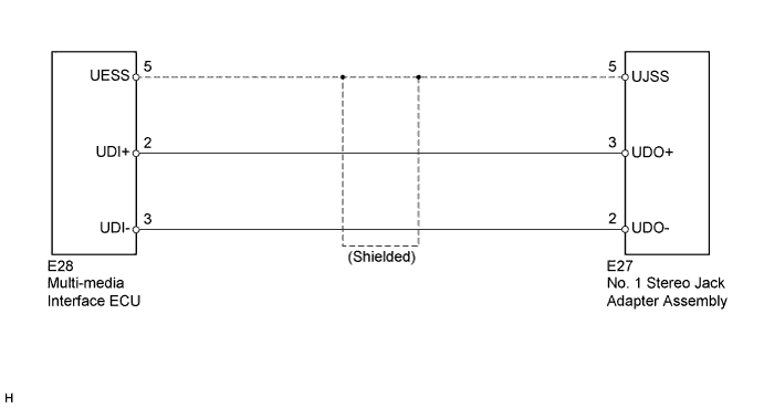
The No. 1 stereo jack adapter assembly sends the sound data from an external device to the multi-media interface ECU through this circuit.
WIRING DIAGRAM
INSPECTION PROCEDURE
PROCEDURE
-
CHECK HARNESS AND CONNECTOR
-
Disconnect the multi-media interface ECU connector.
-
Disconnect the No. 1 stereo jack adapter assembly connector.
-
Measure the resistance according to the value(s) in the table below.
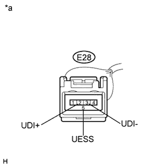
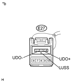
Standard Resistance Tester Connection Condition Specified Condition E27-3 (UDO+) - E28-2 (UDI+) Always Below 1 Ω E27-2 (UDO-) - E28-3 (UDI-) Always Below 1 Ω E27-5 (UJSS) - E28-5 (UESS) Always Below 1 Ω E27-3 (UDO+) - Body ground Always 10 kΩ or higher E27-2 (UDO-) - Body ground Always 10 kΩ or higher E27-5 (UJSS) - Body ground Always 10 kΩ or higher Text in Illustration *a Front view of wire harness connector
(to Multi-media Interface ECU)
*b Front view of wire harness connector
(to No. 1 Stereo Jack Adapter Assembly)
NG 
REPAIR OR REPLACE HARNESS OR CONNECTOR
OK 
PROCEED TO NEXT SUSPECTED AREA SHOWN IN PROBLEM SYMPTOMS TABLE Click here
-