Click here
| DTC Code | DTC Name |
|---|---|
| Television Display Power Source Circuit |
Click here
INSPECTION PROCEDURE
Click here
PROCEDURE
- Click here
CHECK HARNESS AND CONNECTOR (TELEVISION DISPLAY ASSEMBLY - BATTERY, BODY GROUND)
-
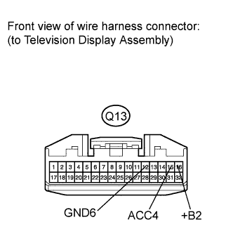
Disconnect the television display assembly connector.
-
Measure the resistance according to the value(s) in the table below.
Standard resistance Tester Connection Condition Specified Condition Q13-12 (GND6) - Body ground Always Below 1 Ω -
Measure the voltage according to the value(s) in the table below.
Standard voltage Tester Connection Condition Specified Condition Q13-16 (+B2) - Body ground Always 11 to 14 V Q13-15 (ACC4) - Body ground Ignition switch on (ACC) 11 to 14 V
- OKClick here
- NGClick here
-
- Click here
PROCEED TO NEXT CIRCUIT INSPECTION SHOWN IN PROBLEM SYMPTOMS TABLEClick here
- Click here
REPAIR OR REPLACE HARNESS OR CONNECTOR