AUDIO AND VISUAL SYSTEM, Diagnostic DTC:CB-13
| DTC Code | DTC Name |
|---|---|
| CB-13 | USB Over Current Detection |
DESCRIPTION
| DTC No. | DTC Detection Condition | Trouble Area |
|---|---|---|
| CB-13 | "iPod" or USB device overcurrent malfunction |
|
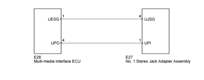
WIRING DIAGRAM
INSPECTION PROCEDURE
PROCEDURE
-
REPLACE USB DEVICE OR "iPod"
-
Disconnect the USB device or "iPod" from the No. 1 stereo jack adapter assembly.
-
Turn the ignition switch off.
Tech Tips
When this DTC has been stored, it is necessary to turn off the ignition switch to make it possible for the vehicle to recognize a new device when it is connected.
-
Turn the ignition switch to ACC.
-
Connect a known good USB device or "iPod" to the No. 1 stereo jack adapter assembly.
NEXT 
-
-
CLEAR DTC
-
Clear the DTCs Click here.
NEXT
-
-
RECHECK FOR DTC
-
Recheck for DTCs and check if the same DTC is output again.
Tech Tips
If DTCs are detected frequently, replace the multi-media interface ECU.
OK No DTCs are output.
NG 
INSPECT MULTI-MEDIA INTERFACE ECU Click here
OK 
USB DEVICE OR "iPod" WAS DEFECTIVE
-
-
INSPECT MULTI-MEDIA INTERFACE ECU
-
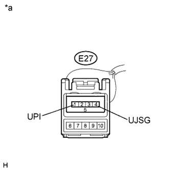
Text in Illustration *a Front view of wire harness connector
(to No. 1 Stereo Jack Adapter Assembly)
Disconnect the No. 1 stereo jack adapter assembly connector.
-
Measure the voltage according to the value(s) in the table below.
Standard Voltage Tester Connection Condition Specified Condition E27-1 (UPI) - E27-4 (UJSG) Ignition switch ACC 5 V
NG
CHECK HARNESS AND CONNECTOR Click here
OK
REPLACE NO. 1 STEREO JACK ADAPTER ASSEMBLY Click here
-
-
CHECK HARNESS AND CONNECTOR
-
Disconnect the multi-media interface ECU connector.
-
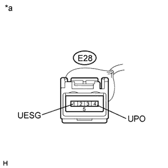
Text in Illustration *a Front view of wire harness connector
(to Multi-media Interface ECU)
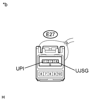
*b Front view of wire harness connector
(to No. 1 Stereo Jack Adapter Assembly)
Measure the resistance according to the value(s) in the table below.
Standard Resistance Tester Connection Condition Specified Condition E28-4 (UPO) - E27-1 (UPI) Always Below 1 Ω E28-1 (UESG) - E27-4 (UJSG) Always Below 1 Ω E27-1 (UPI) - Body ground Always 10 kΩ or higher E27-4 (UJSG) - Body ground Always 10 kΩ or higher
NG 
REPAIR OR REPLACE HARNESS OR CONNECTOR
OK
REPLACE MULTI-MEDIA INTERFACE ECU Click here
-