METER / GAUGE SYSTEM Clock Display Circuit
DESCRIPTION
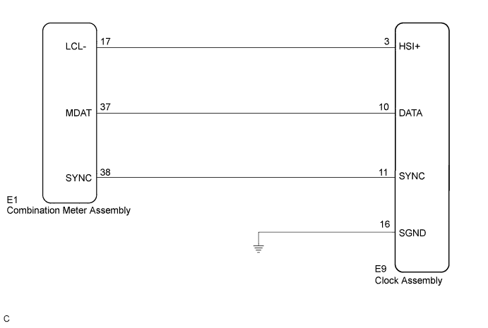
In this circuit, the clock assembly receives a DISP switch signal from the combination meter assembly using the direct line and a multi-information display signal from each ECU through the combination meter assembly using the direct line.
Tech Tips
-
If the vehicle is equipped with the multi-information display, check this circuit.
-
If a system has a malfunction a relevant ECU stores DTCs.
WIRING DIAGRAM
INSPECTION PROCEDURE
PROCEDURE
-
CHECK CAN COMMUNICATION SYSTEM
-
Check if a CAN communication DTC is output Click here.
Result Result Proceed to CAN communication DTC is not output. A CAN communication DTC is output. B
B 
GO TO CAN COMMUNICATION SYSTEM Click here
A 
-
-
CHECK HARNESS AND CONNECTOR (CLOCK ASSEMBLY - COMBINATION METER)
-
Disconnect the E9 and E1 connectors.
-
Measure the resistance according to the value(s) in the table below.
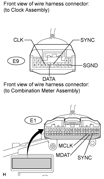
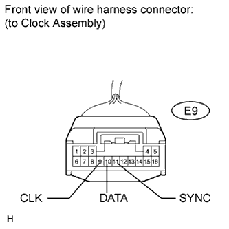
Standard resistance Tester Connection Condition Specified Condition E9-9 (CLK) - E1-36 (MCLK) Always Below 1 Ω E9-10 (DATA) - E1-37 (MDAT) Always Below 1 Ω E9-11 (SYNC) - E1-38 (SYNC) Always Below 1 Ω E9-9 (CLK) - Body ground Always 10 kΩ or higher E9-10 (DATA) - Body ground Always 10 kΩ or higher E9-11 (SYNC) - Body ground Always 10 kΩ or higher E9-16 (SGND) - Body ground Always Below 1 Ω
NG
REPAIR OR REPLACE HARNESS OR CONNECTOR
OK
-
-
INSPECT COMBINATION METER ASSEMBLY
-
Reconnect the E1 connector.
-
Measure the resistance according to the value(s) in the table below.
Standard resistance Tester Connection Condition Specified Condition E9-9 (CLK) - Body ground Ignition switch on (IG) Pulse generation E9-10 (DATA) - Body ground Ignition switch on (IG) Pulse generation E9-11 (SYNC) - Body ground Ignition switch on (IG) Pulse generation
NG
REPLACE COMBINATION METER ASSEMBLY Click here
OK 
REPLACE CLOCK ASSEMBLY Click here
-