METER / GAUGE SYSTEM, Diagnostic DTC:B1500
| DTC Code | DTC Name |
|---|---|
| B1500 | Fuel Sender Open Detected |
DESCRIPTION
This DTC is output when the combination meter assembly detects a fuel sender gauge malfunction via the direct line.
| DTC No. | DTC Detection Condition | Trouble Area |
|---|---|---|
| B1500 | When either of the following conditions is detected:
|
|
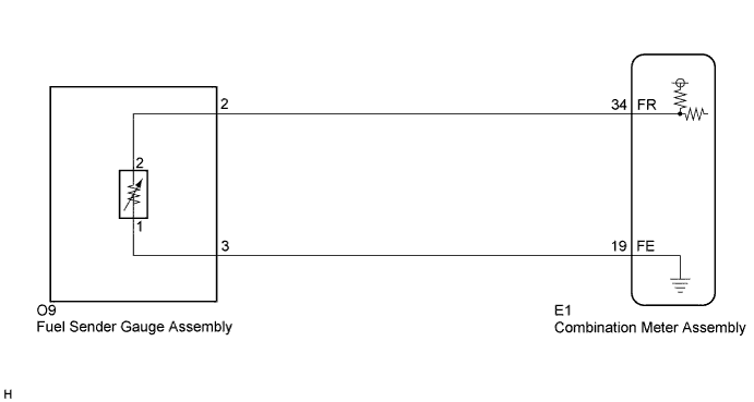
WIRING DIAGRAM
INSPECTION PROCEDURE
PROCEDURE
-
READ VALUE USING INTELLIGENT TESTER (FUEL INPUT)
-
Connect the intelligent tester to the DLC3.
-
Turn the engine switch on (IG).
-
Turn the tester on.
-
Enter following menus: Body / Combination Meter / Data List.
-
Check the values by referring to the table below.
Combination Meter: Tester Display Measurement Item/Range Normal Condition Diagnostic Note Fuel Input Fuel input signal/Min.: 0, Max.: 127.5 Fuel gauge indicates (E): 7.5 (L)
Fuel gauge indicates (1/2): 35.0 (L)
Fuel gauge indicates (F): 62.9 (L)
- Result Result Proceed to Fuel level data can be displayed on the intelligent tester and DTC B1500 is output. A Fuel level data cannot be displayed on the intelligent tester. B
B 
INSPECT COMBINATION METER ASSEMBLY Click here
A 
REPLACE COMBINATION METER ASSEMBLY Click here
-
-
INSPECT COMBINATION METER ASSEMBLY
-
Disconnect the E1 connector.
-
Measure the resistance according to the value(s) in the table below.
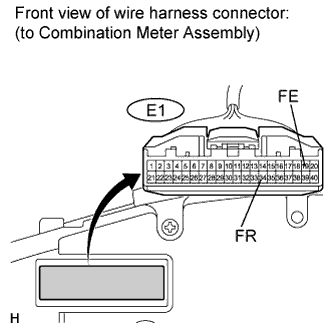
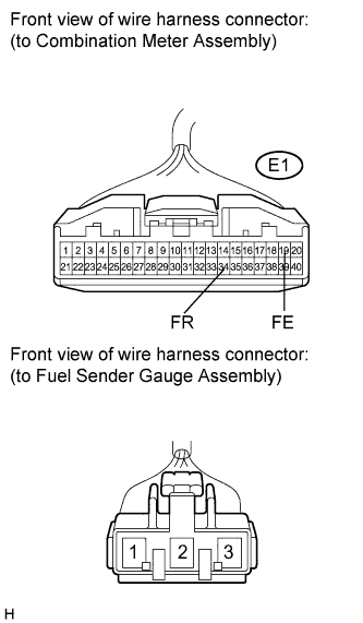
Standard resistance Tester Connection Condition Specified Condition E1-19 (FE) - E1-34 (FR) Always 13.5 to 414.5 Ω
NG
CHECK HARNESS AND CONNECTOR (COMBINATION METER ASSEMBLY - FUEL SENDER GAUGE ASSEMBLY) Click here
OK
REPLACE COMBINATION METER ASSEMBLY Click here
-
-
CHECK HARNESS AND CONNECTOR (COMBINATION METER ASSEMBLY - FUEL SENDER GAUGE ASSEMBLY)
-
Disconnect the fuel sender gauge assembly connector.
-
Measure the resistance according to the value(s) in the table below.
Standard resistance Tester Connection Condition Specified Condition E1-34 (FR) - 2 Always Below 1 Ω E1-34 (FE) - Body ground Always 10 kΩ or higher E1-19 (FE) - 1 Always Below 1 Ω E1-19 (FE) - Body ground Always 10 kΩ or higher
NG 
REPAIR OR REPLACE HARNESS OR CONNECTOR
OK 
-
-
INSPECT FUEL SENDER GAUGE ASSEMBLY
-
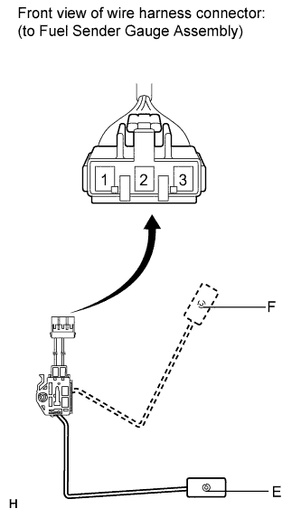
Remove the fuel sender gauge assembly Click here.
-
Check that the float moves smoothly between E and F.
-
Measure the resistance according to the value(s) in the table below.
Standard resistance Tester Connection Condition Specified Condition 1 - 2 Float level is F (upper) 3.0 to 5.0 Ω 1 - 2 Float level is between F (upper) and E (lower) 3.0 to 111.0 Ω (Gradually changes) 1 - 2 Float level is E (lower) 109.0 to 111.0 Ω
NG
REPLACE FUEL SENDER GAUGE ASSEMBLY (for 2GR-FE) Click here
OK
REPLACE COMBINATION METER ASSEMBLY Click here
-