METER / GAUGE SYSTEM SYSTEM DESCRIPTION
-
OUTLINE OF THE COMBINATION METER ASSEMBLY
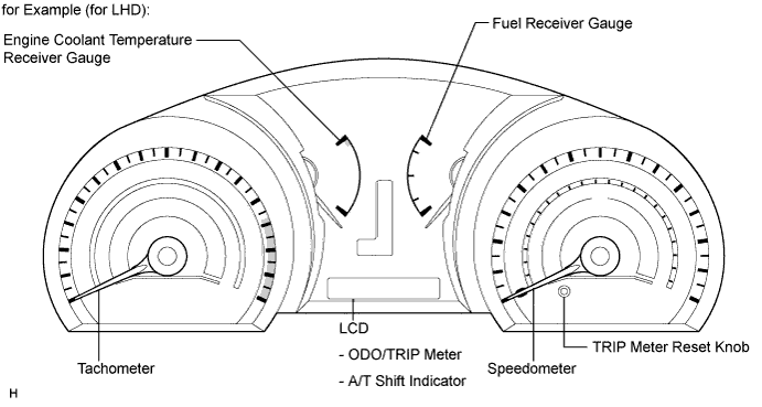
Meter gauge: Item Detail Speedometer Indicates the vehicle speed based on a signal received from the skid control ECU. (CAN (CAN No. 1 Bus)) Tachometer Indicates the engine speed based on a signal received from the ECM. (CAN (CAN No. 1 Bus)) Engine Coolant Temperature Receiver Gauge Indicates the engine coolant temperature based on a signal received from the ECM. (CAN (CAN No. 1 Bus)) Fuel Receiver Gauge Indicates the fuel level based on a fuel level signal received from the fuel sender gauge (Direct Line) and a fuel injection signal and an ST signal received from the ECM. (CAN (CAN No. 1 Bus)) Warning/Indicator: Item Detail Turn Receives a turn signal from the turn signal flasher. (Direct Line) Beam Receives a beam indicator light signal from the main body ECU. (CAN (CAN No. 1 Bus)) Charge Receives a charge indicator light signal from the generator. (Direct Line) MIL (Check engine) Receives a check engine warning light signal from the ECM. (Direct Line) Door Receives a door condition signal from the main body ECU. (CAN (CAN MS Bus)) Driver side seat belt Receives a driver side seat belt signal from the center airbag sensor assembly. (CAN (CAN No. 1 Bus)) Front passenger side seat belt Receives a passenger side seat belt signal from the center airbag sensor assembly and transmits a passenger side seat belt condition signal to the hazard warning switch. (Direct Line) Tail Receives a indicator light signal from the main body ECU. (CAN (CAN No. 1 Bus)) Front fog Receives a front fog indicator light signal from the main body ECU. (CAN (CAN No. 1 Bus)) A/T shift Receives an A/T shift condition signal from the park/neutral position switch and the ECM. (CAN (CAN No. 1 Bus)) A/T fluid temperature Receives an A/T fluid temperature signal from the park/neutral position switch and the ECM. (CAN (CAN No. 1 Bus)) ECT snow Receives an ECT snow signal from the park/neutral position switch and the ECM. (CAN (CAN No. 1 Bus)) Fuel Receives a fuel signal from the fuel sender gauge. (Direct Line) ABS Receives an ABS signal from the skid control ECU. (CAN (CAN No. 1 Bus)) Slip Receives a slip signal from the skid control ECU. (CAN (CAN No. 1 Bus)) Brake Receives a brake signal from the brake fluid level warning switch (Direct Line) and the skid control ECU. (CAN (CAN No. 1 Bus)) Cruise Receives a cruise signal from the ECM. (CAN (CAN No. 1 Bus)) SRS Receives an SRS signal from the center airbag sensor assembly. (CAN (CAN No. 1 Bus)) Downhill assist control (*) Receives a downhill assist control signal from the skid control ECU. (CAN (CAN No. 1 Bus)) VSC off (*) Receives a VSC off signal from the skid control ECU. (CAN (CAN No. 1 Bus)) TRC off Receives a TRC off signal from the skid control ECU. (CAN (CAN No. 1 Bus)) EPS Receives an EPS signal from the power steering ECU. (CAN (CAN No. 1 Bus)) Washer Receives a washer signal from the washer level warning switch. (Direct Line) Master caution indicator light Comes on when the warning display appears. *: for 4WD
-
CLOCK ASSEMBLY (w/ Multi-information Display)
Item Detail Cruise information display
-
Average fuel consumption
-
Current fuel consumption
-
Possible running distance
-
Total cruising distance
-
Total average fuel consumption
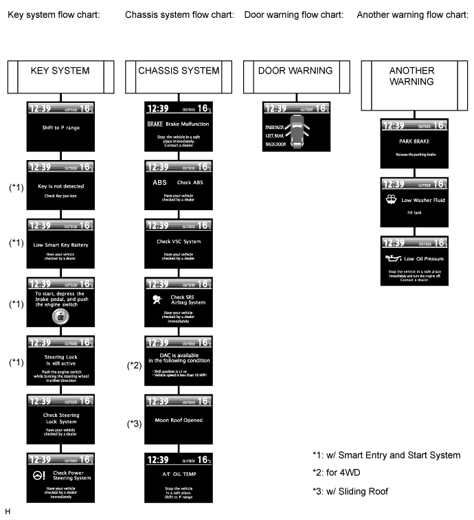
Five types of information (average fuel consumption, current fuel consumption, possible running distance, total cruising distance since reset, and total average fuel consumption since reset) can be displayed. Warning display
-
Door warning
-
Each system warning
Interrupts the multi-information display immediately when a warning occurs. Air conditioning display Interrupts the multi-information display immediately when air conditioning is operated. Rear view monitor display Interrupts the multi-information display immediately when the A/T shift position is moved to R. DTC (Diagnostic Trouble Code) display Displays DTCs pertaining to the VSC function. -
-
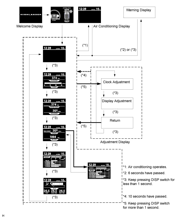
DISPLAY FLOW CHART
Tech Tips
Illustrations may differ from the actual screen displayed depending on the specifications of the vehicle and customized settings.
-
Display flow chart:
-
Each warning mode flow chart:
-
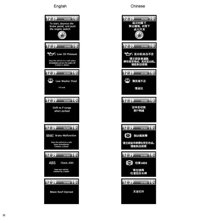
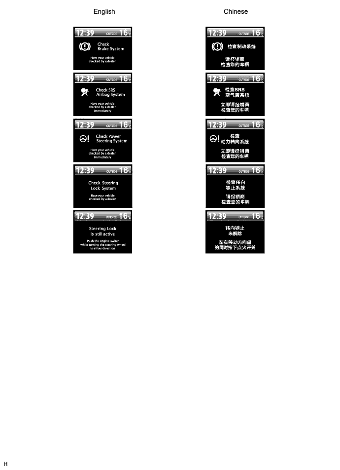
Warning indication for each language:
-
-
LED INITIAL CHECK
-
The illumination function of the warning, indicator, or reminder light listed below can be confirmed when the ignition switch on (IG).
*: for 4WD
-