- Click here
DISCONNECT NEGATIVE BATTERY TERMINAL
CAUTION:Wait at least 90 seconds after disconnecting the cable from the negative (-) battery terminal to prevent airbag and seat belt pretensioner activation (Click here).
Note:When disconnecting the cable, some systems need to be initialized after the cable is reconnected (Click here).
- Click here
REMOVE FRONT DOOR LOWER FRAME BRACKET GARNISH
-
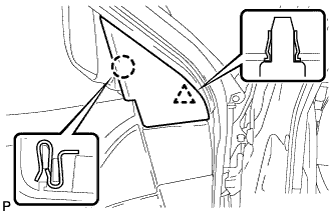
Disengage the claw and clip, and remove the front door lower frame bracket garnish.
-
- Click here
REMOVE FRONT DOOR INSIDE HANDLE BEZEL PLUG
-
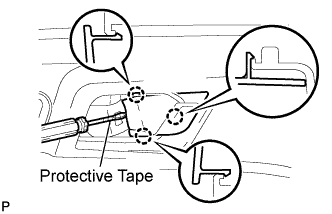
Using a screwdriver with the tip wrapped with protective tape, disengage the 3 claws, and remove the front door inside handle bezel plug.
-
- Click here
REMOVE ASSIST GRIP COVER
-
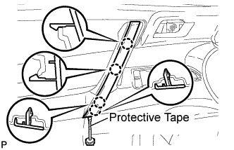
Using a screwdriver with the tip wrapped with protective tape, disengage the 4 claws and remove the assist grip cover.
-
- Click here
REMOVE COURTESY LIGHT ASSEMBLY
-
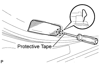
Using a screwdriver with the tip wrapped with protective tape, disengage the claw and remove the courtesy light assembly.
-
Disconnect the connector.
-
- Click here
REMOVE FRONT DOOR TRIM BOARD SUB-ASSEMBLY
-
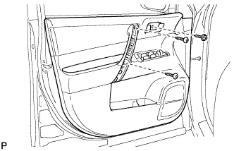
Remove the 3 screws.
-
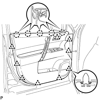
Using a clip remover, disengage the 9 clips.
-
Disengage the 5 claws and separate the front door trim board sub-assembly from the front door inner glass weatherstrip.
-
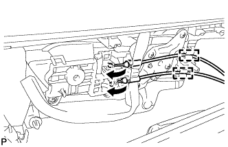
Disengage the 2 clamps.
-
Disconnect the front door lock remote control cable and front door inside locking cable.
-
Disconnect the connector.
-
- Click here
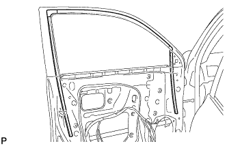
REMOVE FRONT DOOR INNER GLASS WEATHERSTRIP
-
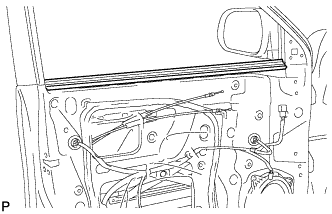
Remove the front door inner glass weatherstrip from the front door panel.
-
- Click here
REMOVE FRONT DOOR SERVICE HOLE COVER
-
Disconnect the each connector and 2 clamps, and remove the front door service hole cover.
Tip:Remove the remaining butyl tape on the door side.
-
- Click here
REMOVE FRONT DOOR GLASS SUB-ASSEMBLY
-
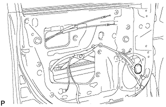
Remove the hole plug.
-
Connect the negative battery terminal.
-
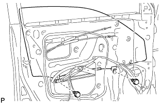
Connect the power window regulator motor connector.
-
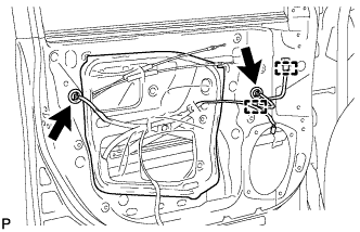
Connect the power window regulator master switch assembly and move the front door glass sub-assembly so that the door glass bolts can be seen.
-
Disconnect the negative battery terminal and power window regulator master switch assembly.
-
Disconnect the power window regulator motor connector.
-
Remove the 2 bolts.
Note:After the bolts are removed, do not allow the door to fall.
-
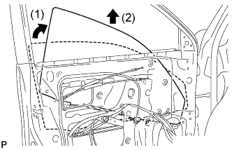
Remove the front door glass sub-assembly as shown in the illustration.
Note:Do not damage the door glass.
-
- Click here
REMOVE FRONT DOOR GLASS RUN
-
Remove the front door glass run.
-
- Click here
REMOVE FRONT DOOR REAR LOWER FRAME SUB-ASSEMBLY
-
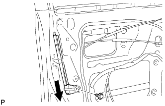
Remove the bolt and the front door rear lower frame sub-assembly as shown in the illustration.
-
- Click here
REMOVE FRONT DOOR OUTSIDE HANDLE COVER (for Driver Side)
-
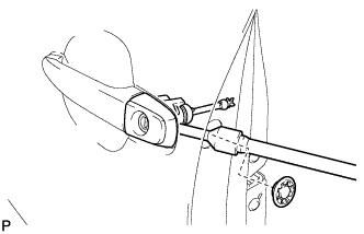
Remove the hole plug.
-
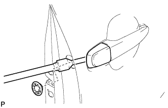
Using a "TORX" socket wrench (T30), loosen the screw and remove the front door outside handle cover and the door lock key cylinder as a unit.
Tip:The screw cannot be removed because it is integrated into the front door outside handle frame sub-assembly.
-
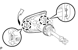
Using a screwdriver, disengage the 2 claws and remove the front door outside handle cover.
-
- Click here
REMOVE FRONT DOOR OUTSIDE HANDLE COVER (for Front Passenger Side)
-
Remove the hole plug.
-
Using a "TORX" socket wrench (T30), loosen the screw and remove the front door outside handle cover and the door lock key cylinder as a unit.
Tip:The screw cannot be removed because it is integrated into the front door outside handle frame sub-assembly.
-
- Click here
REMOVE FRONT DOOR OUTSIDE HANDLE ASSEMBLY
-
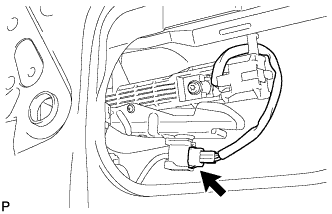
Disconnect the connector.
-
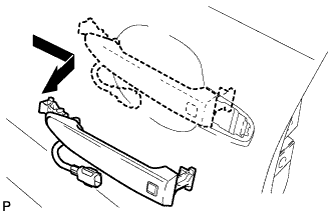
Remove the front door outside handle assembly as shown in the illustration.
-